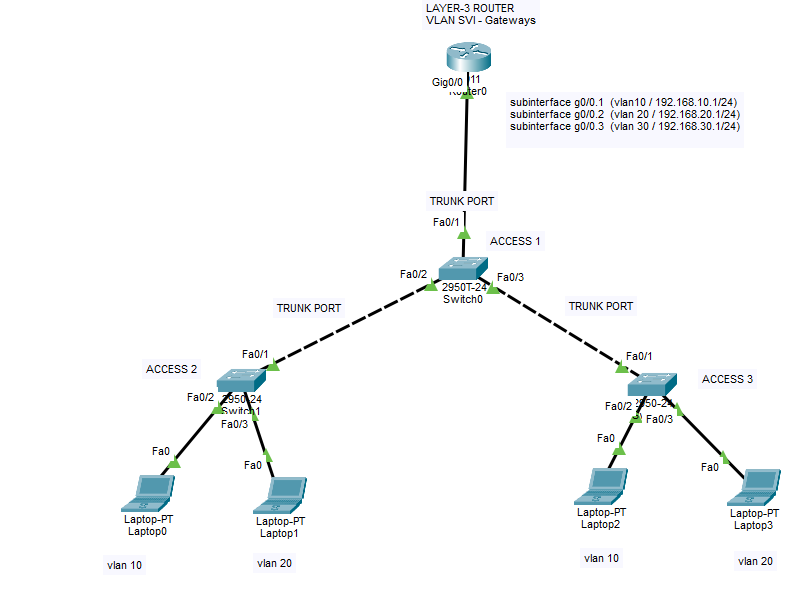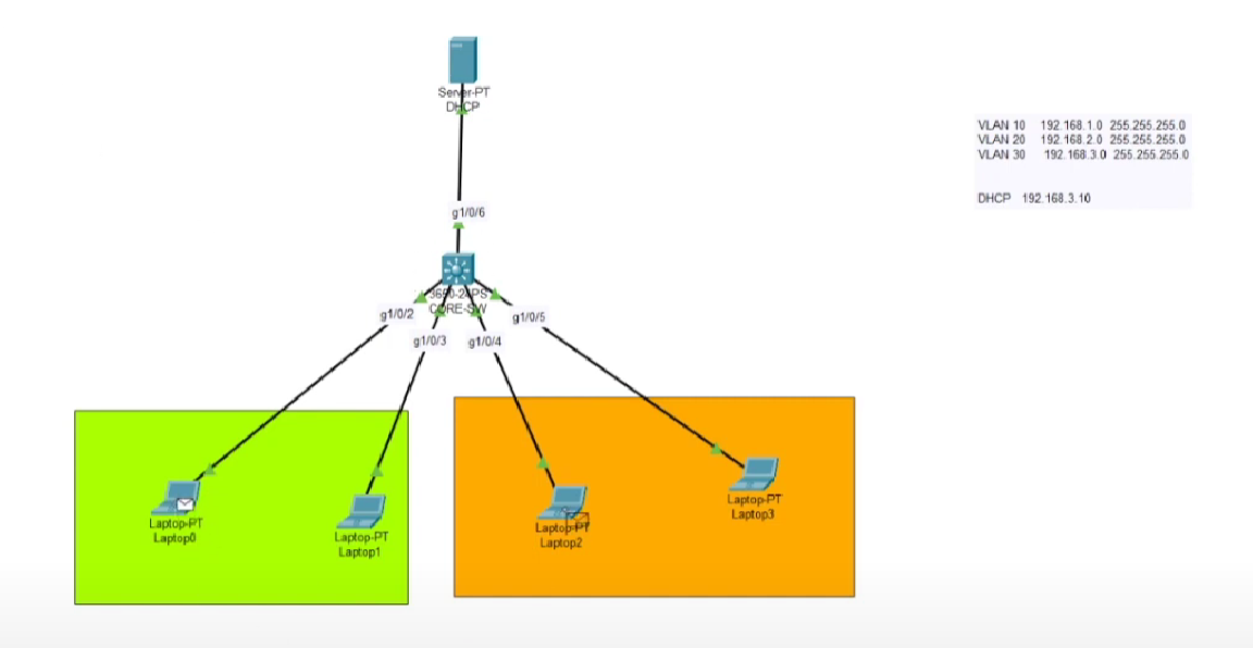
Here you can find the logical topology which was created on Cisco package tracer. There are 3 different VLANs on this system. VLAN 10 is highlighted green, VLAN 2O is highlighted orange and VLAN 30 is used for server management.

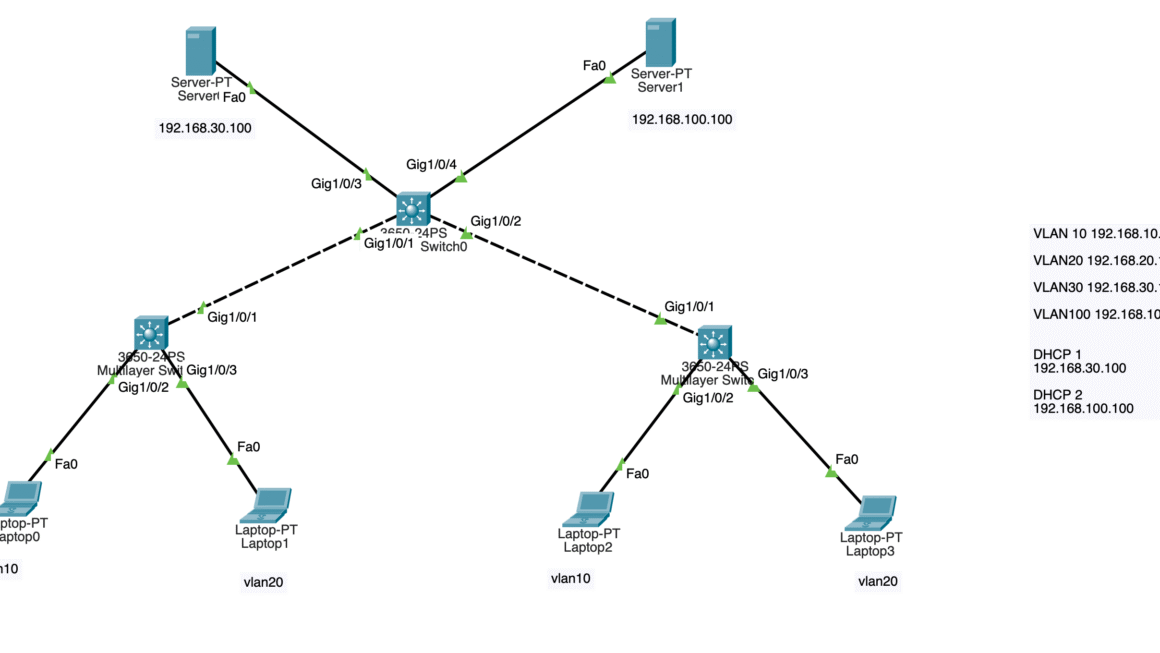
On this network topology, we have 4 clients, 1 layer-3 switch and 1 DHCP server which are connected through the switch with CAT-6 network cable.
Lets begin to configure our system.
Switch>en
Switch#conf terminal
Enter configuration commands, one per line.  End with CNTL/Z.
Switch(config)#vlan 10
Switch(config-vlan)#vlan 20
Switch(config-vlan)#vlan 30
Switch(config-vlan)#exit
Switch(config)#int vlan 10
Switch(config-if)#
%LINK-5-CHANGED: Interface Vlan10, changed state to up

Switch(config-if)#ip address 192.168.1.1 255.255.255.0
Switch(config-if)#no shutdown
Switch(config-if)#ip helper-address 192.168.3.10
Switch(config-if)#exit
Switch(config)#interface vlan 20
Switch(config-if)#
%LINK-5-CHANGED: Interface Vlan20, changed state to up

Switch(config-if)#ip address 192.168.2.1 255.255.255.0
Switch(config-if)#no shutdown
Switch(config-if)#ip helper-address 192.168.3.10
Switch(config-if)#exit
Switch(config)#interface vlan 30
Switch(config-if)#
%LINK-5-CHANGED: Interface Vlan30, changed state to up

Switch(config-if)#ip address 192.168.3.1 255.255.255.0
Switch(config-if)#no shutdown
Switch(config-if)#ip helper-address 192.168.3.10
Switch(config-if)#exit
Switch(config)#ip routing
Switch(config)#do wr
Building configuration...
Compressed configuration from 7383 bytes to 3601 bytes[OK]
[OK]
Switch(config)#
Switch(config)#exit
Switch#
%SYS-5-CONFIG_I: Configured from console by console

Switch#copy running
Switch#copy running-config start
Switch#copy running-config startup-config
Destination filename [startup-config]?
Building configuration...
[OK]
We created VLANs. Right now we need to configure DHCP server and Cisco switch ports.
Switch#configure terminal
Enter configuration commands, one per line.  End with CNTL/Z.
Switch(config)#interface g1/0/6
Switch(config-if)#switchport mode access
Switch(config-if)#switchport access vlan 30
Switch(config-if)#no shutdown
Switch(config-if)#exit
Switch(config)#interface g1/0/2
Switch(config-if)#switchport mode access
Switch(config-if)#switchport access vlan 10
Switch(config-if)#
%LINEPROTO-5-UPDOWN: Line protocol on Interface Vlan10, changed state to up

Switch(config-if)#no shutdown
Switch(config-if)#exit
Switch(config)#interface g1/0/3
Switch(config-if)#switchport mode access
Switch(config-if)#switchport access vlan 10
Switch(config-if)#no shutdown
Switch(config-if)#exit
Switch(config)#interface g1/0/4
Switch(config-if)#switchport mode access
Switch(config-if)#switchport access vlan 20
Switch(config-if)#
%LINEPROTO-5-UPDOWN: Line protocol on Interface Vlan20, changed state to up

Switch(config-if)#no shutdown
Switch(config-if)#exit
Switch(config)#interface g1/0/5
Switch(config-if)#switchport mode access
Switch(config-if)#switchport access vlan 20
Switch(config-if)#no shutdown
Switch(config-if)#exit
Switch(config)#do wr
Building configuration...
Compressed configuration from 7383 bytes to 3601 bytes[OK]
[OK]
Switch(config)#exit
Switch#
%SYS-5-CONFIG_I: Configured from console by console

Switch#copy running-config startup-config
Destination filename [startup-config]?
Building configuration...
[OK]
Switch#
Once we create DHCP scopes with given parameters, our network will work. At the first, nodes won’t be able to ping each other due to updates on ARP tables. But at second try they will communicate.
For DHCP scopes; for each scopes, a VLAN interface IP will be used as a gateway IP. For 192.168.1.0 network; gateway IP will be defined as VLAN interface IP 192.168.1.1. There won’t be any IP pool for VLAN 30 because we plan to use network 30 as server network.
Please feel free to contact me if you have some questions.