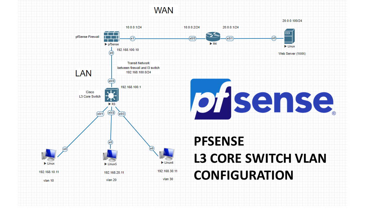
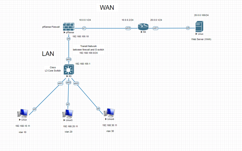
In this lab, we will create 3 vlans and connect our core switch to pfSense firewall with a transit network. Then we will configure our firewall with these vlan subnets. LAN related traffic will not hit the firewall, because SVIs (VLANgateways) will be created on L3 Core switch. All the necessary permissions between vlans will be decided by an ACL on the core switch. All vlans will be able to reach internet through pfSense firewall.
After completing this lab, your Pfsense will pass the WAN traffic from VLANs on Layer 3 switch to outside. And intervlan communication will be held on L3 switch.
Let’s start configuring our Cisco L3 core switch and create vlans.
L3 Core Switch Configuration
Switch>enable
Switch#configure terminal
Enter configuration commands, one per line.  End with CNTL/Z.
Switch(config)#vlan 10
Switch(config-vlan)#vlan 20
Switch(config-vlan)#vlan 30
Switch(config-vlan)#exit

Switch(config)#int vlan 10
Switch(config-if)#ip address 192.168.10.1 255.255.255.0
Switch(config-if)#no shutdown
Switch(config-if)#exit

Switch(config)#int vlan 20
Switch(config-if)#ip address 192.168.20.1 255.255.255.0
Switch(config-if)#no shutdown
Switch(config-if)#exit

Switch(config)#int vlan 30
Switch(config-if)#ip address 192.168.30.1 255.255.255.0
Switch(config-if)#no shutdown
Switch(config-if)#exit

Switch(config)#int e0/1
Switch(config-if)#switchport mode access
Switch(config-if)#switchport access vlan 10
Switch(config-if)#no shutdown
Switch(config-if)#exit

Switch(config)#int e0/2
Switch(config-if)#switchport mode access
Switch(config-if)#switchport access vlan 20
Switch(config-if)#no shutdown
Switch(config-if)#exit

Switch(config)#int e0/3
Switch(config-if)#switchport mode access
Switch(config-if)#switchport access vlan 30
Switch(config-if)#no shutdown
Switch(config-if)#exit

Switch(config)#int e0/0

Switch(config)#int e0/0
Switch(config-if)#no switchport
Switch(config-if)#ip address 192.168.100.1 255.255.255.0
Switch(config-if)#no shutdown
Switch(config-if)#description Transit Network to FW
Switch(config-if)#exit

Switch(config)#ip routing (Inter-VLAN communication)

Switch(config)#ip route 0.0.0.0 0.0.0.0 192.168.100.10 (Routing all traffic to FW)
Switch(config)#do copy run start
Destination filename [startup-config]?
Building configuration...
Compressed configuration from 1131 bytes to 703 bytes[OK]
Switch(config)#
WAN Router Basic Configuration
Router>enable
Router#configure terminal
Enter configuration commands, one per line.  End with CNTL/Z.

Router(config)#int e0/0
Router(config-if)#ip address 10.0.0.2 255.255.255.0
Router(config-if)#no shutdown
Router(config-if)#exit

Router(config)#int e0/1
Router(config-if)#ip address 20.0.0.1 255.255.255.0
Router(config-if)#no shutdown
Router(config-if)#exit

Router(config)#ip routing
Router(config)#do copy run start
Destination filename [startup-config]?
Building configuration...
[OK]
Router(config)#
PfSense Initial CLI Configuration
Use the configuration wizard for interface setups
Set vtnet0 for LAN and IP address 192.168.100.10/24 NO DHCP
Set LAN gateway IP address 192.168.100.1 NO DHCP
Set vtnet1 for WAN and IP address 10.0.0.1/24 NO DHCP
Set WAN gateway IP address 10.0.0.2 NO DHCP
You may also set optional other 2 interfaces if needed.
Once you are done with basics, you can access the GUI via LAN interface IP to proceed to configurations.
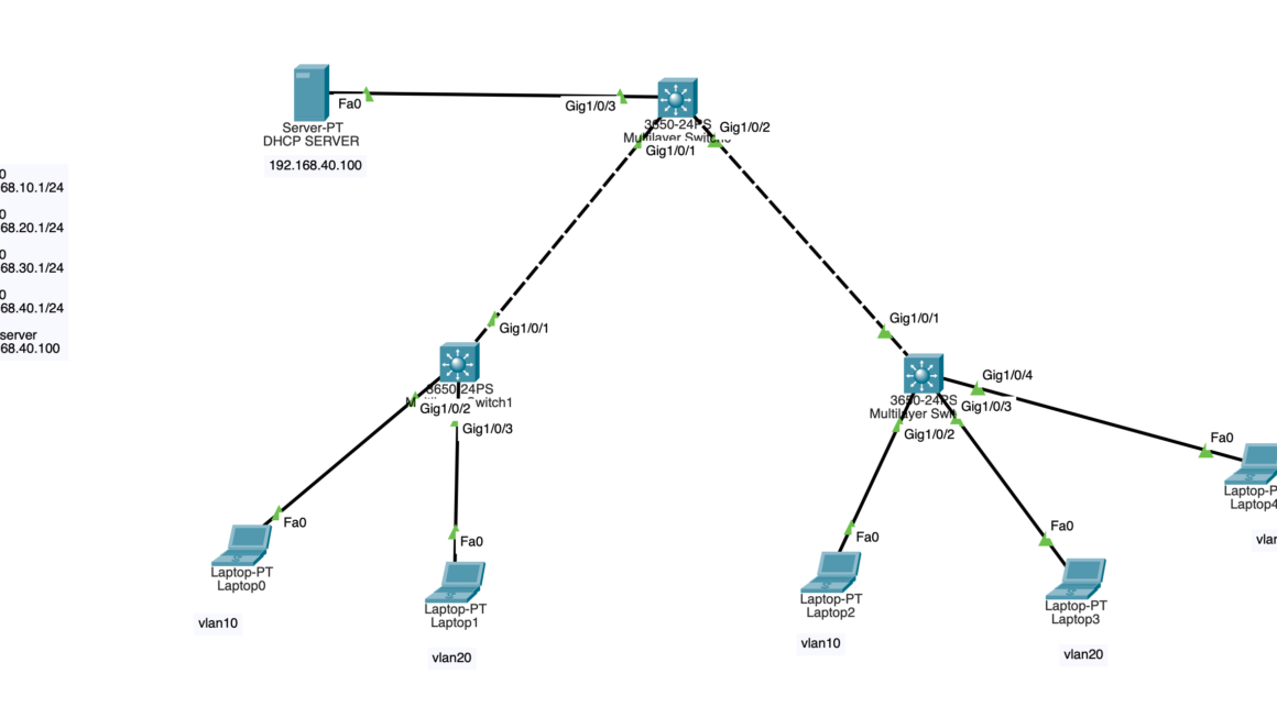
Later you can setup a DHCP IP pool for each vlan either on L3 switch or seperated DHCP server.
(It is easy to configure on Cisco, you can check my previous posts for DHCP server configurations.)
PfSense Main Configurations
To be able to communicate with l3 switch, we had created a TRANSIT NETWORK with network of 192.168.100.0/24
One side will be PfSense LAN interface with IP of 192.168.100.10/24 and the other side will be L3 switch routed port with the IP of 192.168.100.1/24
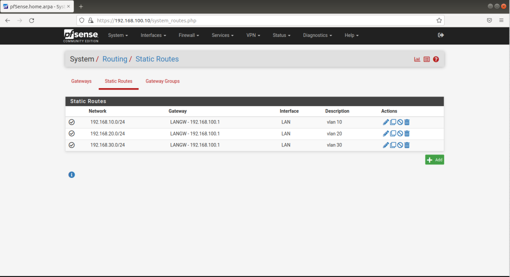
Now we need static routes for all VLAN subnets routed to transit port IP of l3 switch. 192.168.100.1 (Lan Gateway IP which we had already set during CLI initial configuration)
Go to System > Routing > Static Routes and click Add
192.168.10.0/24 to 192.168.100.1 (VLAN 10 gateway to Transit network port on the switch)
192.168.20.0/24 to 192.168.100.1 (VLAN 20 gateway to Transit network port on the switch)
192.168.30.0/24 to 192.168.100.1 (VLAN 30 gateway to Transit network port on the switch)
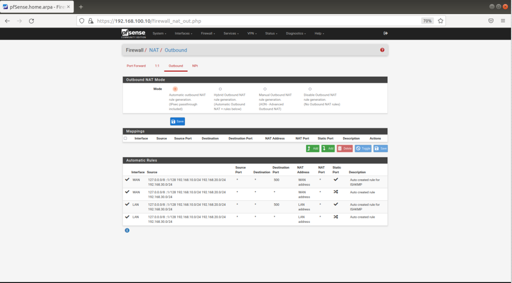
Go to Firewall > NAT > Outbound and check your NAT settings
(should be automatically added)
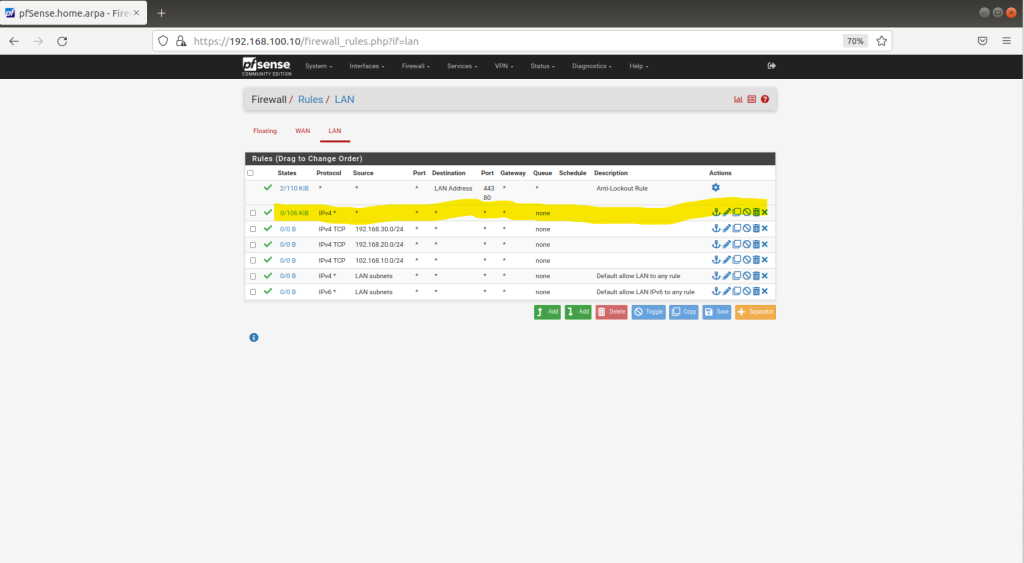
Go to Firewall > Rules > LAN and check IPV4 rules (for this test lab you can enable any to any, just to be able to ping outside free)
Now you should be able to PING outside from any device from any VLAN.
Try to ping 10.0.0.2 from one of your end-devices (any vlan)
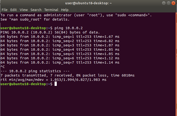
Happy networking and happy new year 🙂