In this post, we will be talking about the Cisco firewall installation and integration with VLANs installed Cisco Core L3 switch. I know, probably most of you had some troubles while you were implementing this topology 🙂 I would like to share all the details that I configured on real devices.
What do we need in our inventory to create this topology;
- Cisco ASA firewall
- Cisco Layer 3 Core switch
- Console cable for configuration (USB to RJ45 console)
- CAT-6 patch cables
- 1 Windows Server for DHCP Server (Not compulsory, DHCP can be installed on ASA or Firewall)
- 2 PCs
- 1 WAN connection (ISP router or home modem etc.)
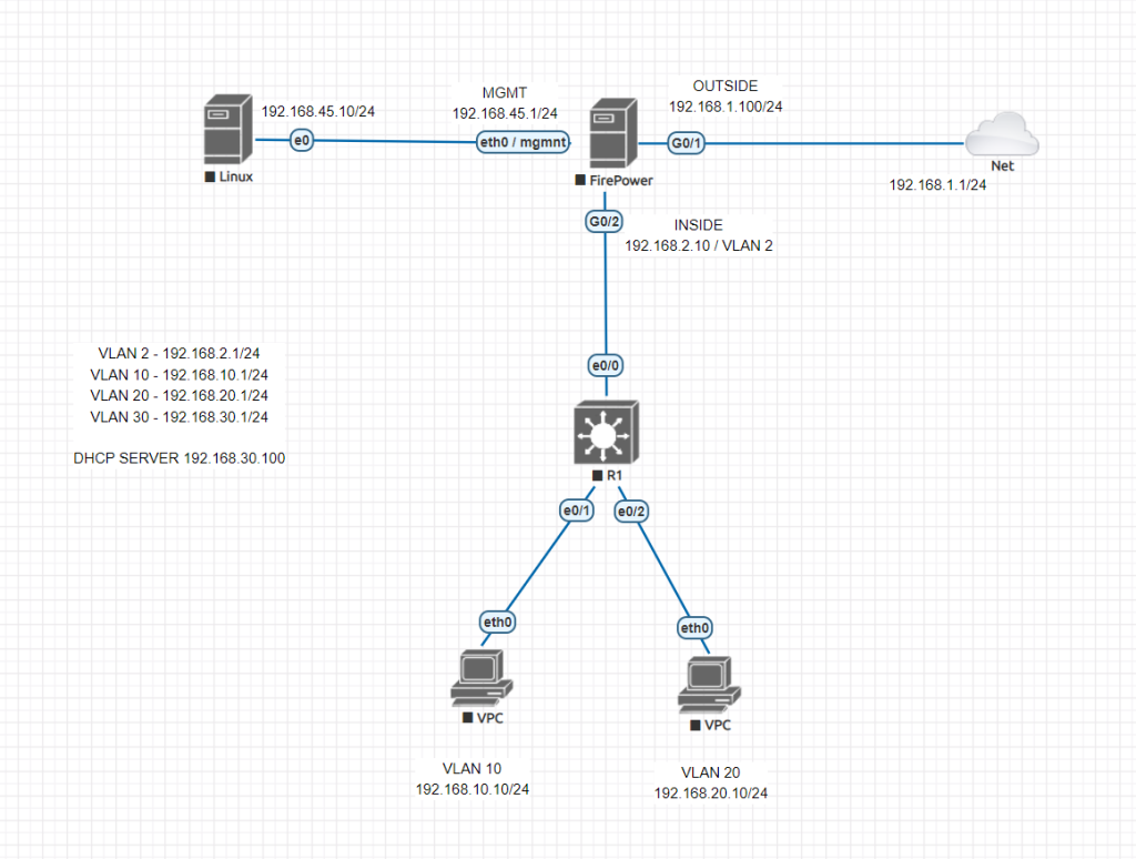
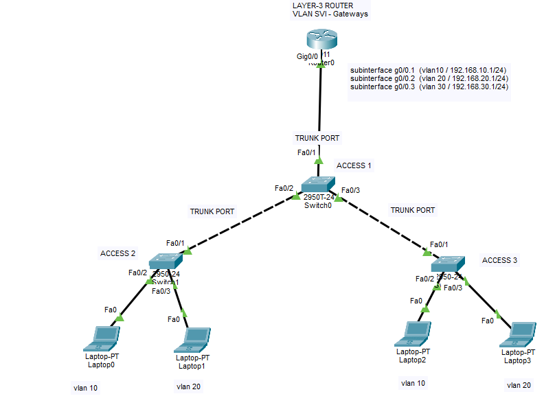
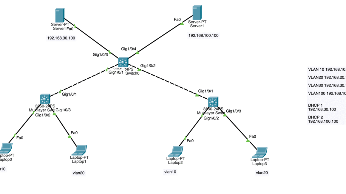
Let’s start with Cisco Layer-3 Switch configuration. We will start configuring VLANs on our core switch and then will connect and route them to firewall using VLAN 2. We will have 4 VLANs. 1 of them is our uplink to firewall, 1 of them is for server use, 2 of them for our clients.
Cisco Core Switch Configuration
Switch>enable
Switch#configure terminal
Enter configuration commands, one per line.  End with CNTL/Z.
Switch(config)#vlan 10
Switch(config-vlan)#vlan 20
Switch(config-vlan)#vlan 30

Switch(config-vlan)#vlan 2
Switch(config-vlan)#exit

Switch(config)#int vlan 10
Switch(config-if)#ip address 192.168.10.1 255.255.255.0
Switch(config-if)#ip helper-address 192.168.30.10
Switch(config-if)#no shutdown
Switch(config-if)#exit

Switch(config)#int vlan 20
Switch(config-if)#ip address 192.168.20.1 255.255.255.0
Switch(config-if)#ip helper-address 192.168.30.10
Switch(config-if)#no shutdown
Switch(config-if)#exit

Switch(config)#int vlan 30
Switch(config-if)#ip address 192.168.30.1 255.255.255.0
Switch(config-if)#ip helper-address 192.168.30.10
Switch(config-if)#no shutdown
Switch(config-if)#exit

Switch(config)#int vlan 2
Switch(config-if)#ip address 192.168.2.1 255.255.255.0
Switch(config-if)#no shutdown
Switch(config-if)#exit

Switch(config)#
Switch(config)#
Switch(config)#int eth0/1
Switch(config-if)#switchport mode access
Switch(config-if)#switchport access vlan 10
Switch(config-if)#no shutdown
Switch(config-if)#exit

Switch(config)#int eth0/2
Switch(config-if)#switchport mode access
Switch(config-if)#switchport access vlan 20
Switch(config-if)#no shutdown
Switch(config-if)#exit

Switch(config)#int eth0/3    # FOR DHCP SERVER ACCESS
Switch(config-if)#switchport mode access
Switch(config-if)#switchport access vlan 30
Switch(config-if)#no shutdown
Switch(config-if)#exit

Switch(config)#do wr
Building configuration...
[OK]
Switch(config)#

Switch(config)#int eth0/0
Switch(config-if)#sw mode acc
Switch(config-if)#sw acc vlan 2
Switch(config-if)#exit
Switch(config)#do wr
Building configuration...
[OK]
Switch(config)#ip routing
Switch(config)#do wr
Building configuration...
[OK]
Switch(config)#ip route 0.0.0.0 0.0.0.0 192.168.2.10  # Firewall UPLINK
Switch(config)#do wr
Building configuration...
[OK]
Switch(config)#
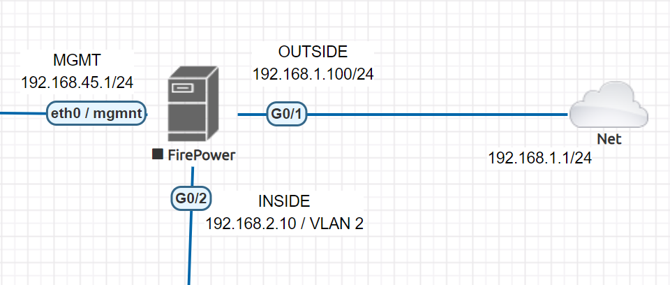
Cisco ASA / Firepower CLI initial configuration
ciscoasa(config)# no dhcpd enable inside
ciscoasa(config)# no dhcpd enable outside

## REMOVE CURRENT DHCP SERVER AND POOLS FOR OUR INSIDE AND OUTSIDE INTERFACES !! ##
ciscoasa(config)#

ciscoasa(config)#
ciscoasa(config)# int eth1/1
ciscoasa(config-if)# nameif outside
ciscoasa(config-if)# ip address 192.168.1.100 255.255.255.0
ciscoasa(config-if)# no shutdown
ciscoasa(config-if)# exit

ciscoasa(config)# int eth1/2
ciscoasa(config-if)# nameif inside
ciscoasa(config-if)# ip address 192.168.2.10 255.255.255.0
ciscoasa(config-if)# no shutdown
ciscoasa(config-if)# exit
ciscoasa(config)#
ciscoasa(config-if)#interface vlan 1
## Change it to some different IP to not to overlap with our configuration
ciscoasa(config-if)#ip address 10.0.0.1 255.0.0.0
Access to Cisco ASA through Management Port with Console cable. Use 192.168.45.x /24 IP to access 192.168.45.1 interface. No default password, you can create a password at this phase.
Download Java SDK and Cisco ASDM-IDM management software to interact with your firewall.
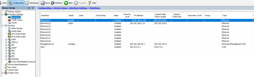
Check your interfaces
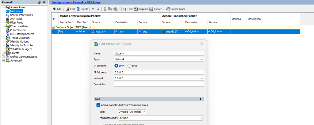
Check your NAT configuration, default NAT configuration is sufficient for internet access
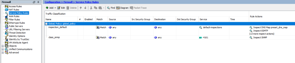
Check your Service Policy Rules and add ICMP for inspection to enable pinging from end-user devices.
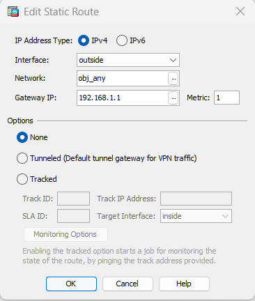
Create static routes for inside VLANs and outside. Outside route will be created as 0.0.0.0 0.0.0.0 to ISP router Gateway 192.168.1.1/24. And VLAN subnets will be routed to our firewall IP link VLAN’s SVI IP as 192.168.2.1/24
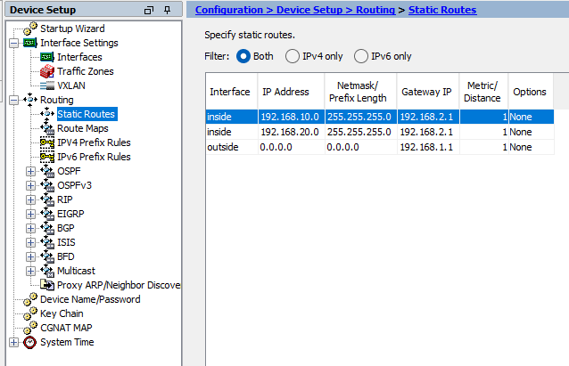
Outside Route to ISP router
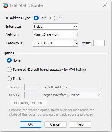
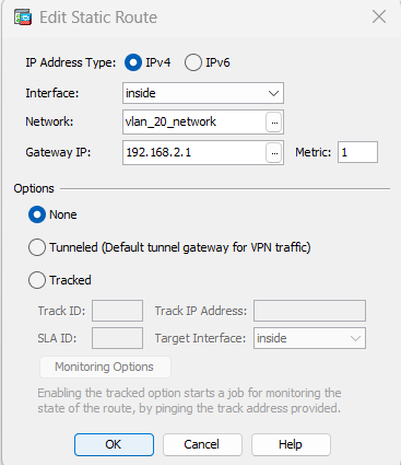
Inside Route for each VLAN subnet to firewall uplinked VLAN’s SVI IP.
VLAN 10 route to VLAN 2 SVI IP
VLAN 20 route to VLAN 2 SVI IP
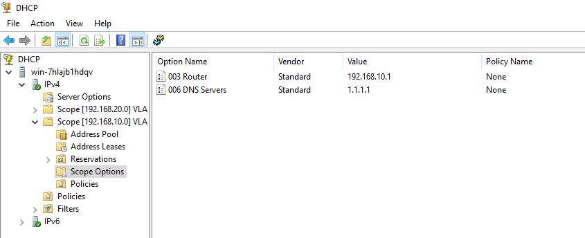
And finally, create DHCP server with below parameters and do not forget to add DNS Server to your scopes. Otherwise end-users cannot resolute domain names. You may use 1.1.1.1 or 8.8.8.8 for test purposes.
VLAN 10 > 192.168.10.1 255.255.255.0
VLAN 20 > 192.168.20.1 255.255.255.0
Do not create DHCP scope for VLAN 30 and VLAN 2, these are for servers and firewall uplink.
Plese do not hesitate to contact me if you have questions regarding this deployment.
Happy networking 🙂