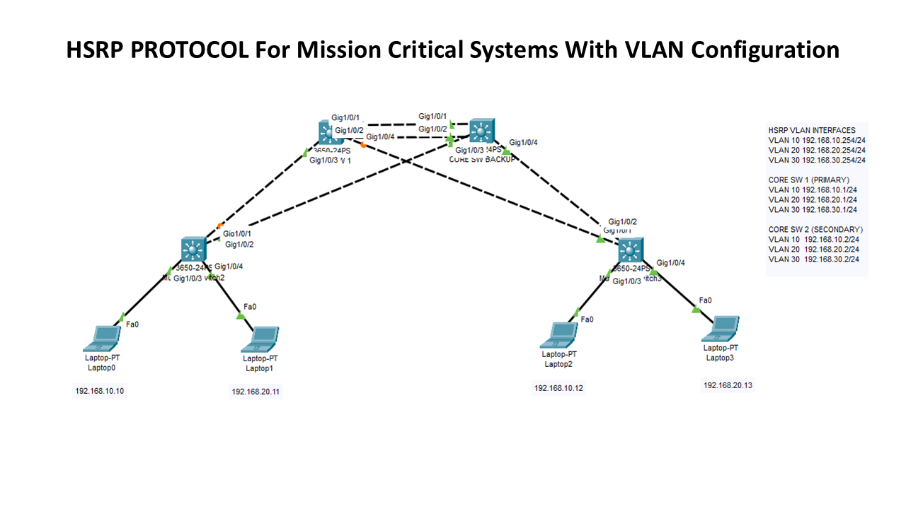
In this lab, we will use HSRP protocol to create high availability for our topology using two core switches as primary and secondary (backup) in case of a failure. By this way, we will avoid single point of failure and eliminate the system downtime.
HSRP (Hot Standby Router Protocol) is a redundancy protocol developed by Cisco to provide high availability for network gateways. It ensures that if one core switch (primary) fails, another (secondary) automatically takes over, minimizing downtime.
On this topology, we have one Cisco L3 core switch which will act as primary core switch and Cisco L3 core switch as secondary backup which will be able to take over all the load if first switch fails. Also we have 2 access switches for end user connections. Below IP addresses will be used for HSRP interfaces and VLAN SVIs.
HSRP INTERFACES
VLAN 10 192.168.10.254/24
VLAN 20 192.168.20.254/24
VLAN 30 192.168.30.254/24
CORE SW 1 (PRIMARY)
VLAN 10 192.168.10.1/24
VLAN 20 192.168.20.1/24
VLAN 30 192.168.30.1/24
CORE SW 2 (SECONDARY)
VLAN 10 192.168.10.2/24
VLAN 20 192.168.20.2/24
VLAN 30 192.168.30.2/24
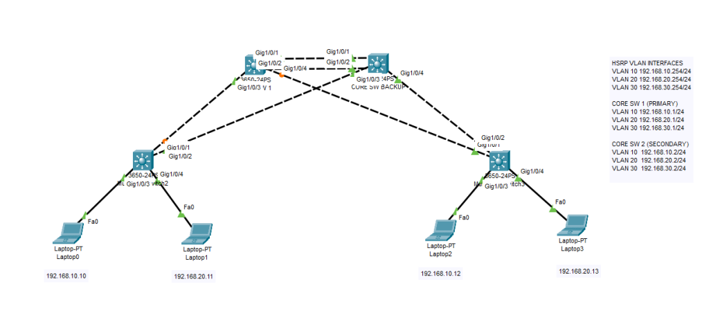
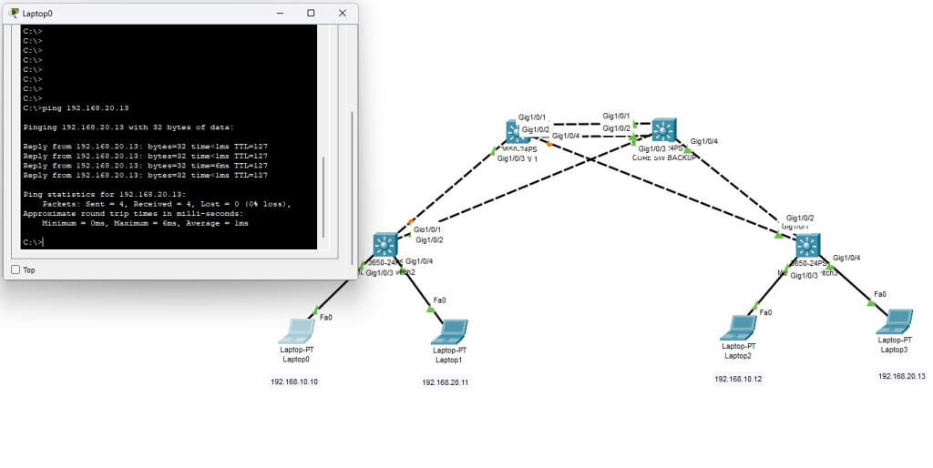
Our topology is as below which can be extended later with more access (distribution) switches;
CORE SWITCH 1 (PRIMARY) CONFIGURATION
enable
configure terminal

vlan 10
 name Users
vlan 20
 name Servers
vlan 30
 name Developers

interface GigabitEthernet1/0/1
 description Trunk to Core SW2
 switchport mode trunk
 switchport trunk allowed vlan 10,20,30

interface GigabitEthernet1/0/2
 description Trunk to Core SW2
 switchport mode trunk
 switchport trunk allowed vlan 10,20,30


interface GigabitEthernet1/0/3
 description Trunk to Access SW1
 switchport mode trunk
 switchport trunk allowed vlan 10,20,30

interface GigabitEthernet1/0/4
 description Trunk to Access SW2
 switchport mode trunk
 switchport trunk allowed vlan 10,20,30

vtp mode transparent
vtp domain Corporate

ip routing

interface vlan 10
 ip address 192.168.10.1 255.255.255.0
interface vlan 20
 ip address 192.168.20.1 255.255.255.0
interface vlan 30
 ip address 192.168.30.1 255.255.255.0


interface vlan 10
 standby 1 ip 192.168.10.254
 standby 1 priority 110
interface vlan 20
 standby 2 ip 192.168.20.254
 standby 2 priority 110
interface vlan 30
 standby 3 ip 192.168.30.254
 standby 3 priority 110
CORE SWITCH 2 (SECONDARY´-Backup Switch) CONFIGURATION
enable
configure terminal
vlan 10
name Users
vlan 20
name Servers
vlan 30
name Developers
interface GigabitEthernet1/0/1
description Trunk to Core SW1
switchport mode trunk
switchport trunk allowed vlan 10,20,30
interface GigabitEthernet1/0/2
description Trunk to Core SW1
switchport mode trunk
switchport trunk allowed vlan 10,20,30
interface GigabitEthernet1/0/3
description Trunk to Access SW 1
switchport mode trunk
switchport trunk allowed vlan 10,20,30
interface GigabitEthernet1/0/4
description Trunk to Access SW 2
switchport mode trunk
switchport trunk allowed vlan 10,20,30
vtp mode transparent
vtp domain Corporate
ip routing
interface vlan 10
ip address 192.168.10.2 255.255.255.0
interface vlan 20
ip address 192.168.20.2 255.255.255.0
interface vlan 30
ip address 192.168.30.2 255.255.255.0
interface vlan 10
standby 1 ip 192.168.10.254
standby 1 priority 90
interface vlan 20
standby 2 ip 192.168.20.254
standby 2 priority 90
interface vlan 30
standby 3 ip 192.168.30.254
standby 3 priority 90
ACCESS SWITCH 1 CONFIGURATION (LEFT)
enable
configure terminal
vlan 10
name Users
vlan 20
name Servers
vlan 30
name Developers
interface g1/0/3
switchport access vlan 10
switchport mode access
interface g1/0/4
switchport access vlan 20
switchport mode access
interface GigabitEthernet1/0/1
description Trunk to Core SW 1
switchport mode trunk
switchport trunk allowed vlan 10,20,30
interface GigabitEthernet1/0/2
description Trunk to Core SW 2
switchport mode trunk
switchport trunk allowed vlan 10,20,30
ACCESS SWITCH 2 CONFIGURATION (RIGHT)
enable
configure terminal
vlan 10
name Users
vlan 20
name Servers
vlan 30
name Developers
interface g1/0/3
switchport access vlan 10
switchport mode access
interface g1/0/4
switchport access vlan 20
switchport mode access
interface GigabitEthernet1/0/1
description Trunk to Core SW 1
switchport mode trunk
switchport trunk allowed vlan 10,20,30
interface GigabitEthernet1/0/2
description Trunk to Core SW 2
switchport mode trunk
switchport trunk allowed vlan 10,20,30
KEY POINTS TO REMEMBER
Unlike conventional systems with VLAN infrastructure, we won’t set VLAN SVI gateways on DHCP server as 192.168.10.1 or 192.168.10.2 . Instead we will use HSRP Interface IP to be able to communicate over VLANs. Inver-VLAN communication will take place over a virtual IP which has HA ability. Set your DHCP scope accordingly with 192.168.10.254/24, 192.168.20.254/24, 192.168.30.254/24 as shown on config.
Please do not hesitate to contact me if you have any further technical questions. I will be happy to answer them.
HAPPY NETWORKING 🙂