Setting up an IPSEC VPN tunnel between two sites is a great way to securely connect them. It allows for secure communication between the two sites and helps protect data from being intercepted. IPSEC VPN tunnels on Fortigate firewalls are easy to setup and configure, and can be done with the help of Cisco or Fortinet’s SSL configuration tools. In this article, we will discuss how to create an IPSEC VPN tunnel on a Fortigate firewall, what settings need to be configured, and how to ensure that it is working properly. We will also provide some tips on troubleshooting any issues that may arise during the setup process.
IMPORTANT NOTE:
Please bear in mind that creating IPSEC VPN tunnels requires careful network/subnet planning for enterprise networks !
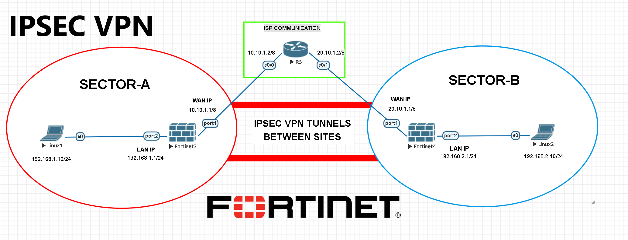
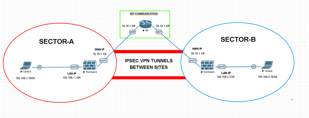
Here below in this example; we will create IPSEC VPN tunnels between two far location sites with Fortigate Firewall. There are 2 firewalls, 2 linux vpcs and 1 ISP router used on this topology.
Okay here we go ! We will start configuring our Fortigate Firewalls like as before. Configurations will be simple and basic. Written IPs will be given to necessary interfaces, static routes will be created and afterwards we will make some preparations for the IPSEC VPN tunnels.
Once we set manual IP address to clients as mentioned above, we can start to configure firewall side via CLI with console access.
Fortigate FW Default username : admin
Fortigate FW Default password : (empty) System will force you to create a new password once you log in.
SECTOR – A / FIREWALL CONFIGURATIONS
CHANGING HOSTNAME AND TIMEZONE
config system global
set alias SECTOR_A_FW
set hostname SECTOR_A_FW
set timezone 31 ## This is Istanbul Timezone
end
DNS CONFIGURATION
You may use your local DNS server instead of below IPs.
config system dns
set primary 1.1.1.1
set secondary 8.8.8.8
end
LAN INTERFACE
config system interface
edit port2
set mode static
set ip 192.168.1.1 255.255.255.0 ## Static IP for LAN int.
set allowaccess ping https ssh http fgfm ## open ports for LAN
set alias LAN ## This is a given name, can be changed.
set role lan ## Role for this interface
end
WAN INTERFACE
config system interface
edit port1
set mode static
set ip 10.10.1.1 255.0.0.0 ## Static IP for WAN int.
set allowaccess ping https ssh http fgfm ## open ports for WAN
set alias WAN ## This is a given name, can be changed.
set role wan ## Role for this interface
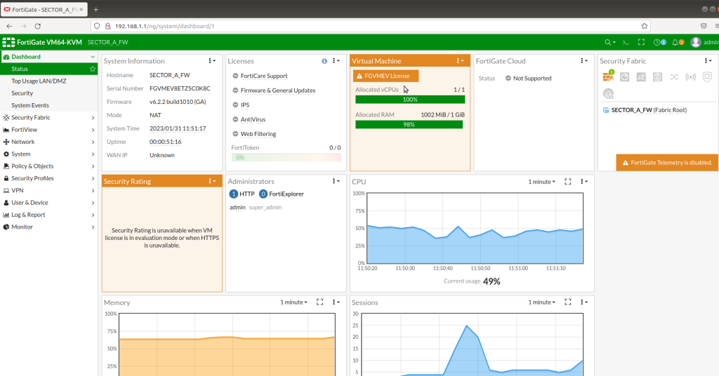
endAfter completing this configuration, you will be able to access Fortigate Firewall GUI through LAN interface IP.
Normally we do not take care of ISP routing for sure. But to make this example more realistic we will make a basic routing with a Cisco router. Follow the basic router configurations as below. Otherwise two sites cannot communicate.
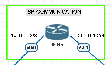
ISP ROUTER CONFIGURATION BETWEEN SITES

Router>enable
Router#configure terminal
Enter configuration commands, one per line.  End with CNTL/Z.
Router(config)#ip routing

Router(config)#int e0/0
Router(config-if)#ip address 10.10.1.2 255.0.0.0
Router(config-if)#no shutdown
Router(config-if)#exit

Router(config)#int e0/1
Router(config-if)#ip address 20.10.1.2 255.0.0.0
Router(config-if)#no shutdown
Router(config-if)#exit

Router(config)#do wr
Building configuration...
[OK]
Router(config)#
After completing ISP Router configurations, we jump into Fortigate configs.
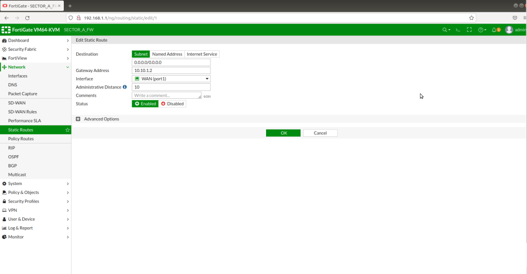
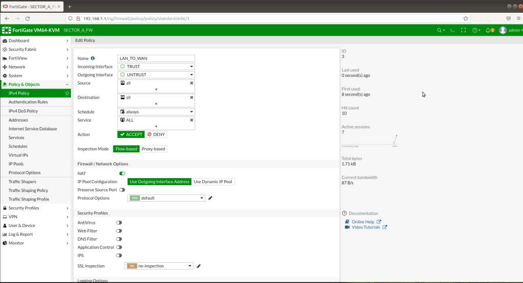
Static route from LAN interface to WAN interface has to be defined in order to give access to LAN clients. Also a policy from LAN (trust zone) to WAN (untrust zone) has to be created with necessary service settings as below. In this example, I let all the clients able to access internet without any restrictions.
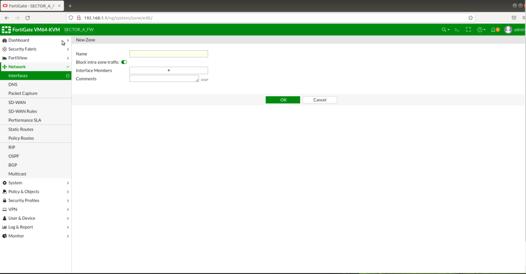
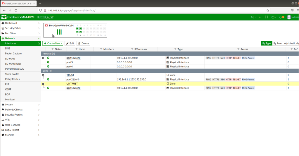
We need to create 2 different zones including LAN and WAN interfaces from “Zones” section. Trust zone will be our LAN interface(192.168.1.1/24) and Untrust zone will be our WAN interface (10.10.1.1/8).
After successfully creating zones, now we need to create IPSEC VPN Tunnels. In order to create a tunnel, go to VPN > IPSEC Tunnels > Create new tunnel > then follow the instructions below as in the picture.
STEP -1
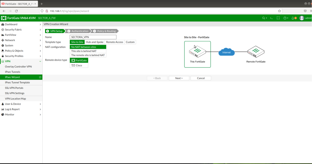
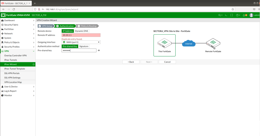
STEP -2
At this step, you are supposed to set a “pre-shared key” which will be used for both sites to make sure connections will be safe while establishing.
STEP -3
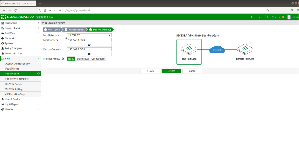
Once we hit the “Create” button, “”voila !!!” IPSEC VPN tunnel is ready for access.
Same configuration has to be done for SECTOR – B as mentioned in SECTOR – A example.
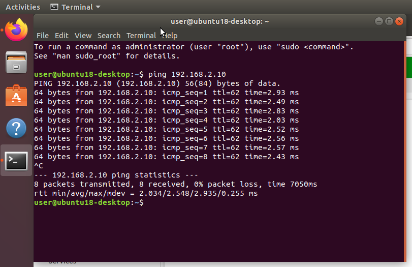
You can try to ping from each site.
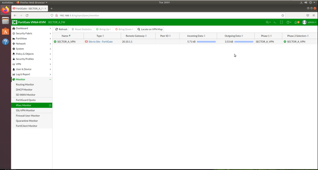
You can always watch your IPSEC VPN traffic between the sites, using IPSEC Monitor feature under Monitor tab.
Please always feel free to contact me regarding your system and network related questions.
Wish you a great day 🙂