Configuring a Fortigate Firewall is an important step for any network administrator. It not only ensures that the firewall is set up correctly, but also helps keep the network secure from any potential threats. In this article, we will discuss how to configure a Fortigate Firewall using CLI, from its first setup to more advanced configurations. We will also discuss some of the best practices for configuring your Fortigate Firewall and how to troubleshoot any issues that may arise during configuration.
At first phase, we start to configure Fortigate firewall using CLI with RS232 console connection. We do all the necessary interface and static routing configurations before we move to next phase. This is important because once we implement VLANs on Cisco switches. Otherwise you won’t be able to reach the firewall LAN interface.
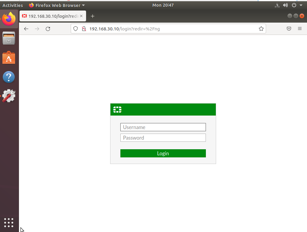
Fortigate FW Default username : admin
Fortigate FW Default password : (empty) System will force you to create a new password once you log in.
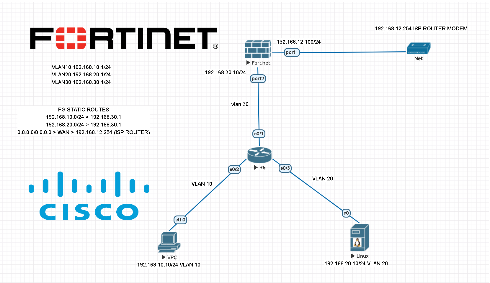
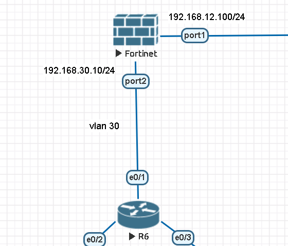
Here is the logical topology which we would like to create. Once you implement this topology, you can easily add multiple VLAN clients to the network.
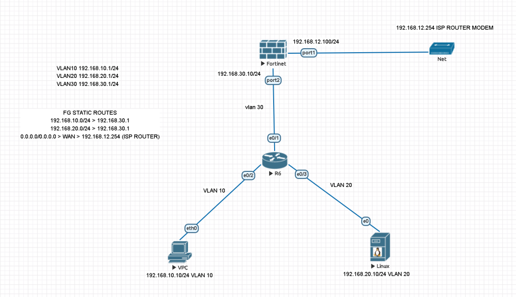
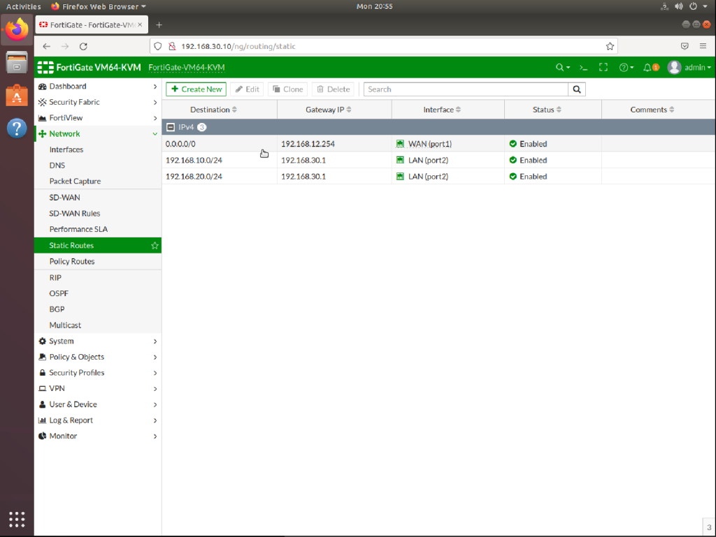
FG STATIC ROUTES
192.168.10.0/24 > 192.168.30.1
192.168.20.0/24 > 192.168.30.1
0.0.0.0/0.0.0.0 > WAN > 192.168.12.254 (ISP ROUTER)
VLAN SUBNETS
VLAN10 192.168.10.1/24
VLAN20 192.168.20.1/24
VLAN30 192.168.30.1/24 (FOR FORTIGATE LINK)
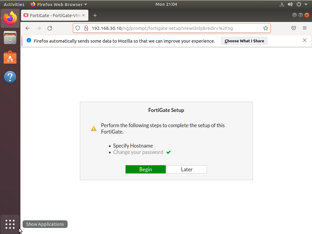
CHANGING HOSTNAME AND TIMEZONE
config system global
set alias "FortigateVM"
set hostname "FortigateVM"
set timezone 31 ## This is Istanbul Timezone
end
DNS CONFIGURATION
You may use your local DNS server instead of below IPs.
config system dns
set primary 1.1.1.1
set secondary 8.8.8.8
end
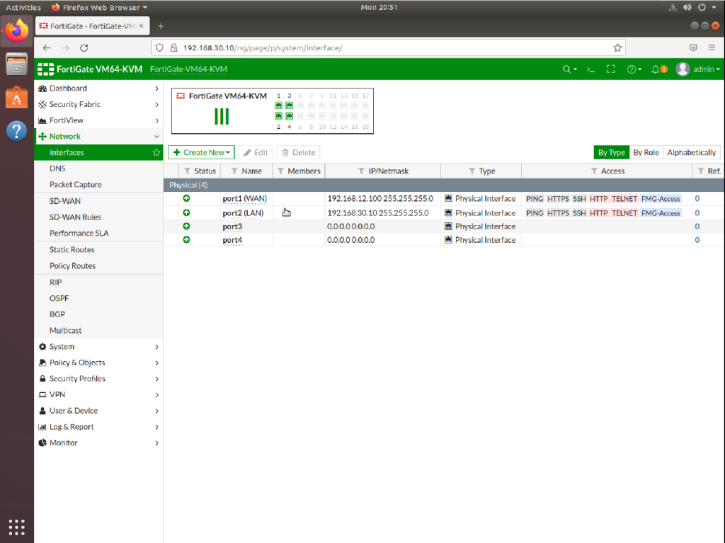
LAN INTERFACE
config system interface
edit port2
set mode static
set ip 192.168.30.10 255.255.255.0 ## Static IP for LAN int.
set allowaccess ping https ssh http fgfm ## open ports for LAN
set alias LAN ## This is a given name, can be changed.
set role lan ## Role for this interface
end
WAN INTERFACE
config system interface
edit port1
set mode static
set ip 192.168.12.100 255.255.255.0 ## Static IP for WAN int.
set allowaccess ping https ssh http fgfm ## open ports for WAN
set alias WAN ## This is a given name, can be changed.
set role wan ## Role for this interface
end
Now we can reach to Fortigate firewall from both Port1 and Port2 and do the necessary static routing configurations.
Now everything is done at the firewall side. We can proceed to create VLANs on Cisco core switch. We assume that we have only one layer 3 switch on this topology. If you have more than one switch and would like to use them with trunking, please make sure that your VTP server is this core switch. If you create VLANs on another switch or at the firewall, you will face some issues then you will have to change your switch from VTP client to VTP server.
Here how we configure Cisco VLANs below,
MOST IMPORTANT NOTE: Static routes for VLANS are important otherwise you cannot reach to FW GUI from your vlan access ports. Thus, create static routes for all VLAN subnets with the gateway IP of Firewall Linked IP’s VLAN interface IP (192.168.30.1). So all VLANs can access to VLAN 30.
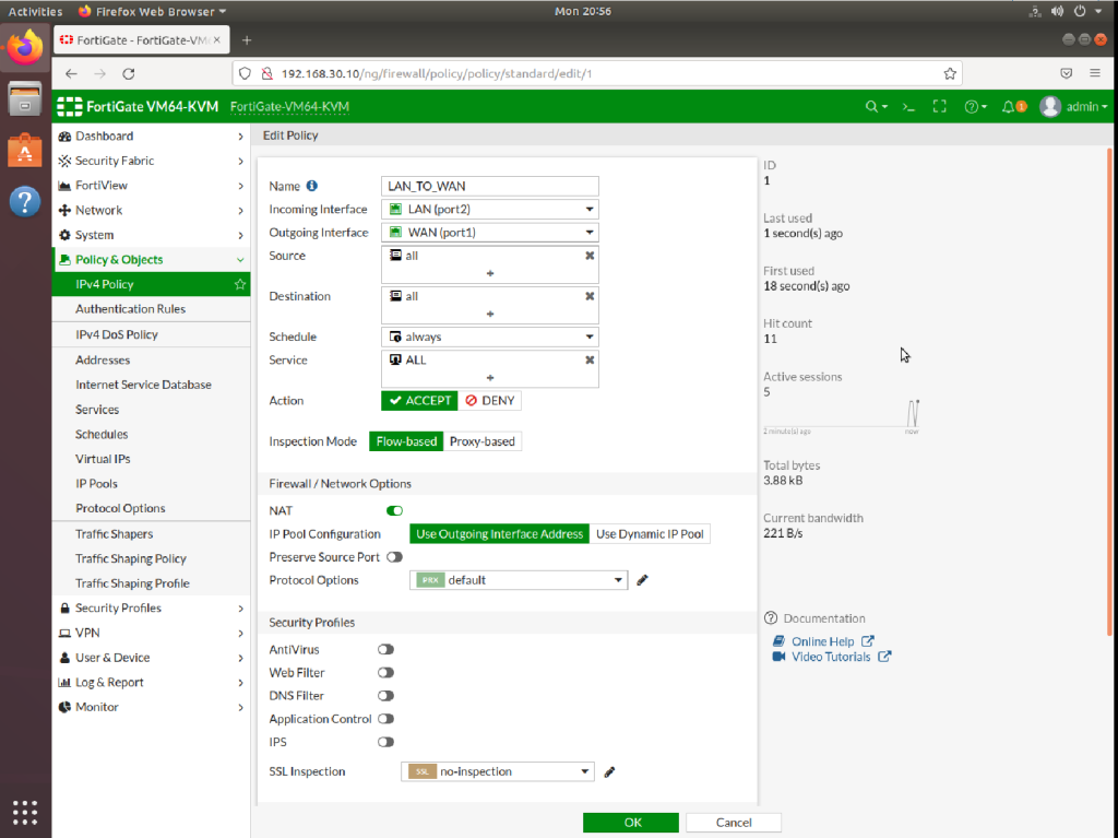
ADD 2 IPV4 POLICY.
LAN_TO_WAN policy should be added as above. And LAN_TO_LAN policy should be added via Incoming source : LAN and Outgoing source: LAN and all services should be added. With this LAN policy you can ping each other end devices.
AND DO NOT FORGET TO ENABLE “ip routing” command otherwise intervlan communication will not be possible. And at the end double check if you have entered “ip route 0.0.0.0 0.0.0.0 192.168.30.10” to divert all necessary network traffic to Firewall LAN interface (port2).
Switch>en
Switch#configuration terminal
Enter configuration commands, one per line.  End with CNTL/Z.
Switch(config)#hostname SW1
SW1(config)#vlan 10
SW1(config-vlan)#vlan 20
SW1(config-vlan)#vlan 30
SW1(config-vlan)#exit
SW1(config)#interface vlan 10
SW1(config-if)#
%LINK-5-CHANGED: Interface Vlan10, changed state to up

SW1(config-if)#ip address 192.168.10.1 255.255.255.0
SW1(config-if)#no shutdown
SW1(config-if)#exit
SW1(config)#interface vlan 20
SW1(config-if)#
%LINK-5-CHANGED: Interface Vlan20, changed state to up

SW1(config-if)#ip address 192.168.20.1 255.255.255.0
SW1(config-if)#no shutdown
SW1(config-if)#exit
SW1(config)#interface vlan 30
SW1(config-if)#
%LINK-5-CHANGED: Interface Vlan30, changed state to up

SW1(config-if)#ip address 192.168.30.1 255.255.255.0
SW1(config-if)#no shutdown
SW1(config-if)#exit

SW1(config)#do wr

SW1(config)#interface eth0/1  ## FIREWALL LAN INTERFACE LINK
SW1(config-if)#switchport mode access
SW1(config-if)#switchport access vlan 30
SW1(config-if)#no shutdown
SW1(config-if)#exit


SW1(config)#interface eth0/2
SW1(config-if)#switchport mode access
SW1(config-if)#switchport access vlan 10
SW1(config-if)#no shutdown
SW1(config-if)#exit
SW1(config)#interface eth0/3
SW1(config-if)#switchport mode access
SW1(config-if)#switchport access vlan 20
SW1(config-if)#no shutdown
SW1(config-if)#exit
SW1(config)#do wr
SW1#

SW1(config)#ip routing   ## ENABLE INTER-VLAN COMMUNICATION
SW1(config)#ip route 0.0.0.0 0.0.0.0 192.168.30.10 ##ROUTING TRAFFIC TO FW
CISCO CORE SWITCH SHOW RUNNING-CONFIG

Switch#
Switch#en
Switch#sh run
Building configuration...

Current configuration : 1790 bytes
!
version 15.1
service timestamps debug datetime msec
service timestamps log datetime msec
no service password-encryption
service compress-config
!
hostname Switch
!
boot-start-marker
boot-end-marker
!
!
!
no aaa new-model
!
ip cef
!
!
no ipv6 cef
ipv6 multicast rpf use-bgp
!
!
!
!
!
!
!
spanning-tree mode pvst
spanning-tree extend system-id
!
!
!
!
vlan internal allocation policy ascending
!
!
!
!
!
!
!
!
!
!
interface Ethernet0/0
 duplex auto
!
interface Ethernet0/1
 switchport access vlan 30
 switchport mode access
 duplex auto
!
interface Ethernet0/2
 switchport access vlan 10
 switchport mode access
 duplex auto
!
interface Ethernet0/3
 switchport access vlan 20
 switchport mode access
 duplex auto
!
interface Ethernet1/0
 duplex auto
!
interface Ethernet1/1
 duplex auto
!
interface Ethernet1/2
 duplex auto
!
interface Ethernet1/3
 duplex auto
!
interface Ethernet2/0
 duplex auto
!
interface Ethernet2/1
 duplex auto
!
interface Ethernet2/2
 duplex auto
!
interface Ethernet2/3
 duplex auto
!
interface Ethernet3/0
 duplex auto
!
interface Ethernet3/1
 duplex auto
!
interface Ethernet3/2
 duplex auto
!
interface Ethernet3/3
 duplex auto
!
interface Serial4/0
 no ip address
 shutdown
 no fair-queue
 serial restart-delay 0
!
interface Serial4/1
 no ip address
 shutdown
 serial restart-delay 0
!
interface Serial4/2
 no ip address
 shutdown
 serial restart-delay 0
!
interface Serial4/3
 no ip address
 shutdown
 serial restart-delay 0
!
interface Vlan10
 ip address 192.168.10.1 255.255.255.0
!
interface Vlan20
 ip address 192.168.20.1 255.255.255.0
!
interface Vlan30
 ip address 192.168.30.1 255.255.255.0
!
!
no ip http server
!
ip route 0.0.0.0 0.0.0.0 192.168.30.10
!
!
!
!
control-plane
!
!
line con 0
 logging synchronous
line aux 0
line vty 0 4
 login
!
end
I hope this network simulation clears your mind about using Cisco switches with Fortigate. You can always ask your questions about system and network related topics, I will be happy to assist you.
For this emulated virtual network environment I used EVE-NG network simulator which is very hardware source effective, I strongly suggest all IT people to use this lightweight source effective open source software. Easy to install and everything is real 🙂