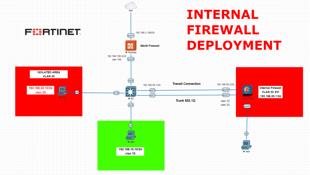
An internal firewall, also known as an internal network firewall or a segment firewall, is a security system designed to protect and control traffic between different segments within an organization’s internal network. Unlike a perimeter firewall, which protects the network from external threats, an internal firewall focuses on securing the internal network by regulating the flow of data between different departments, subnets, or internal systems. Here are some key features and functions of an internal firewall:
We will follow below order while configuring our environment,
-Main firewall configurations LAN and WAN and then interfaces, static routes, ipv4 policies
-Core switch configurations and port allocations, VLAN SVI creation for VLAN 10, assigning ports for routing mode, VLAN access definitions and static routes to both internal firewall and main firewall
-Internal firewall configurations with Transit LAN, Trunk and static route. We will set VLAN 20 SVI here. Then we will configure IPV4 policies to access other devices.
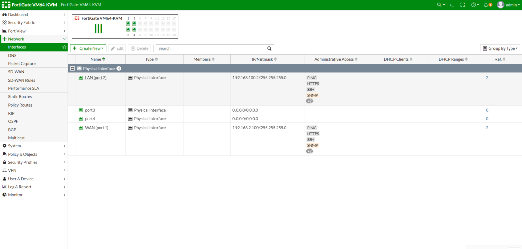
Main Firewall Configuration
config system interface
edit port1
set alias WAN
set role wan
set mode static
set ip 192.168.2.100 255.255.255.0
set allowaccess http https ssh ping telnet snmp
next
edit port2
set alias LAN
set role lan
set mode static
set ip 192.168.100.2 255.255.255.0 // This port will be defined as VLAN 100 on the switch as access port.
set allowaccess http https ssh ping telnet snmp
end
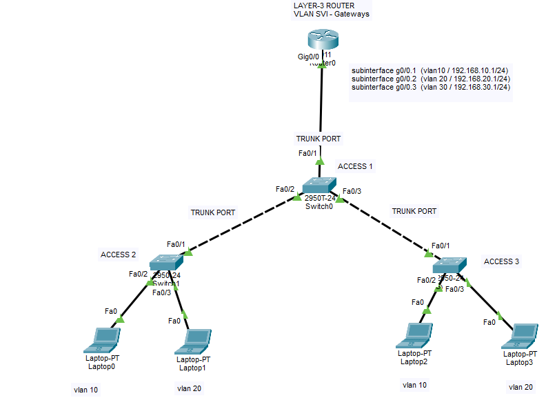
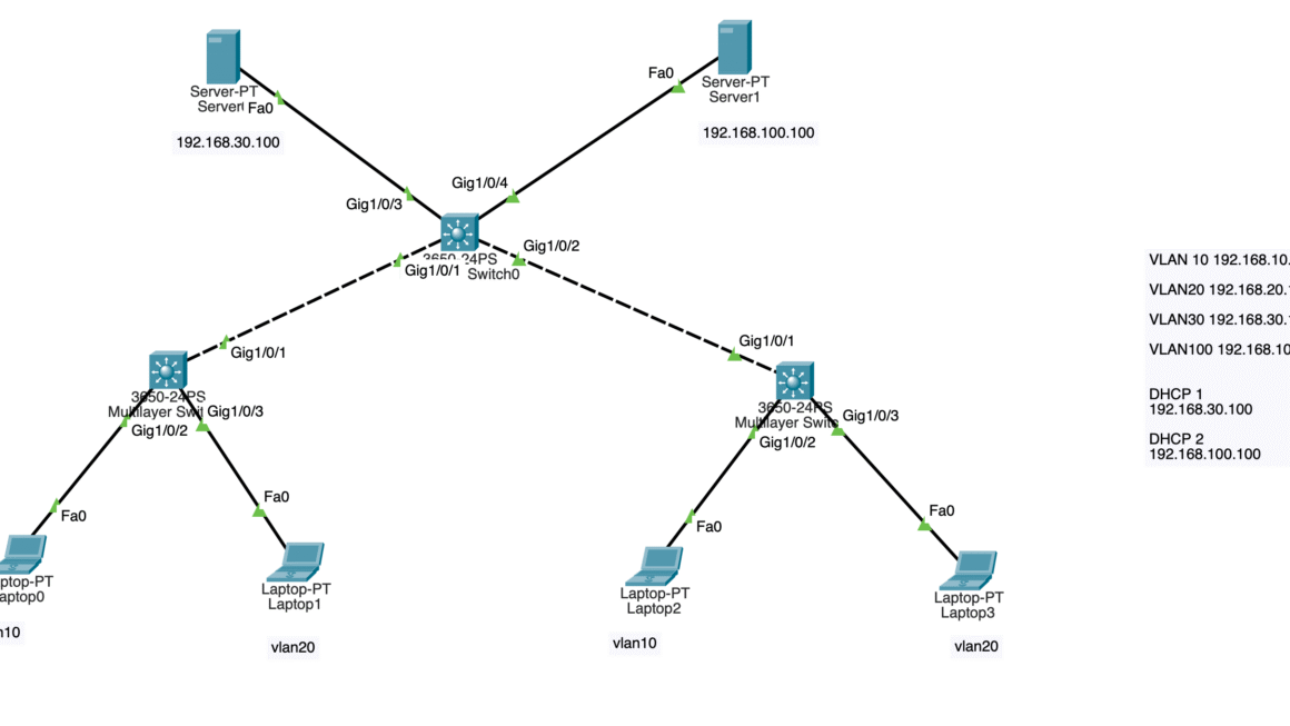
Core Switch Configurations
Switch>en
Switch#conf t
Enter configuration commands, one per line. End with CNTL/Z.
Switch(config)#vlan 10
Switch(config-vlan)#ex
Switch(config)#vlan 20
Switch(config-vlan)#vlan 100
Switch(config-vlan)#ex
Switch(config)#int vlan 10
Switch(config-if)#ip address 19
*Jul 14 12:52:57.817: %LINEPROTO-5-UPDOWN: Line protocol on Interface Vlan10, changed state to down
Switch(config-if)#ip address 192.168.10.1 255.255.255.0
Switch(config-if)#no sh
Switch(config-if)#ex
Switch(config)#int v
*Jul 14 12:53:20.970: %LINK-3-UPDOWN: Interface Vlan10, changed state to down
Switch(config)#int vlan 100
Switch(config-if)#ip addres
*Jul 14 12:53:26.262: %LINEPROTO-5-UPDOWN: Line protocol on Interface Vlan100, changed state to down
Switch(config-if)#ip address 192.168.100.1 255.255.255.0
Switch(config-if)#no sh
Switch(config-if)#ex
Switch(config)#int
*Jul 14 12:53:43.466: %LINK-3-UPDOWN: Interface Vlan100, changed state to down
Switch(config)#int e0/0
Switch(config-if)#sw mode acc
Switch(config-if)#sw acc vlan 100
Switch(config-if)#no sh
Switch(config-if)#ex
Switch(config)#int e1/0
Switch(config-if)#sw mode acc
Switch(config-if)#sw acc vlan 20
Switch(config-if)#no sh
Switch(config-if)#ex
Switch(config)#vlan 20
Switch(config-vlan)#ex
Switch(config)#int e0/2
Switch(config-if)#sw mode acc
Switch(config-if)#sw acc vlan 10
Switch(config-if)#no sh
Switch(config-if)#ex
Switch(config)#int e0/3
Switch(config-if)#no s
*Jul 14 12:54:31.454: %LINK-3-UPDOWN: Interface Vlan100, changed state to up
*Jul 14 12:54:32.454: %LINEPROTO-5-UPDOWN: Line protocol on Interface Vlan100, changed state to up
Switch(config-if)#no switchport
Switch(config-if)#ip address 192
*Jul 14 12:54:41.432: %LINK-3-UPDOWN: Interface Ethernet0/3, changed state to up
*Jul 14 12:54:42.433: %LINEPROTO-5-UPDOWN: Line protocol on Interface Ethernet0/3, changed state to up
Switch(config-if)#ip address 192.168.50.1 255.255.255.0
Switch(config-if)#no sh
Switch(config-if)#ex
Switch(config)#
*Jul 14 12:55:00.252: %LINK-3-UPDOWN: Interface Vlan10, changed state to up
*Jul 14 12:55:01.256: %LINEPROTO-5-UPDOWN: Line protocol on Interface Vlan10, changed state to up
Switch(config)#int e0/1
Switch(config-if)#sw mode trunk
Command rejected: An interface whose trunk encapsulation is "Auto" can not be configured to "trunk" mode.
Switch(config-if)#sw trunk encapsulation dot1q
Switch(config-if)#sw mode trunk
Switch(config-if)#
*Jul 14 12:55:37.892: %LINEPROTO-5-UPDOWN: Line protocol on Interface Ethernet0/1, changed state to down
Switch(config-if)#sw trunk allow vlan all
*Jul 14 12:55:43.318: %LINEPROTO-5-UPDOWN: Line protocol on Interface Ethernet0/1, changed state to up
Switch(config-if)#sw trunk allow vlan 10,20
Switch(config-if)#no sh
Switch(config-if)#ex
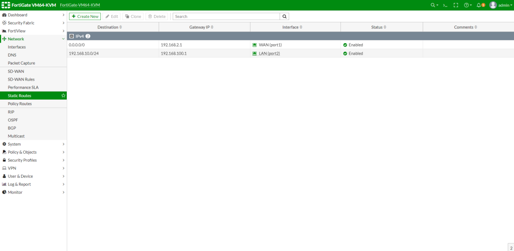
Switch(config)#ip route 0.0.0.0 0.0.0.0 192.168.100.2
Switch(config)#ip route 192.168.20.0 255.255.255.0 192.168.50.2
Switch(config)#do copy run start
Destination filename [startup-config]?
Building configuration...
Compressed configuration from 1334 bytes to 784 bytes[OK]
Switch(config)#
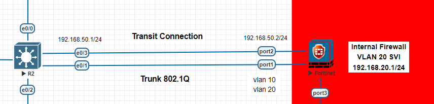
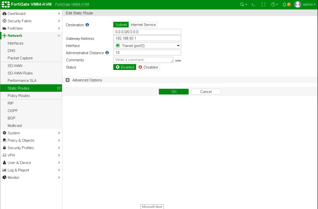
Route all the internet traffic as 0.0.0.0 0.0.0.0 192.168.100.2 to main firewall. Then route VLAN 20 subnet traffic to 192.168.50.2 to our internal firewall transit leg. Ip route 192.168.20.0 255.255.255.0 192.168.50.2
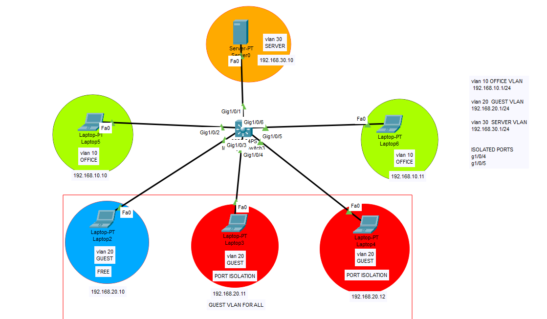
Basically on the core switch, we created 3 VLANs. One for Main firewall access VLAN 100, and VLAN 10 for our other subnet. Then VLAN 20 as layer2 vlan, we will create VLAN 20 SVI on internal firewall. Then we assigned access ports to 2 devices and firewall connection. Then we set a transit connection via port e0/3 as routed mode and Trunk port to pass trunk data to internal firewall via e0/1 port.
Internal Firewall Configurations
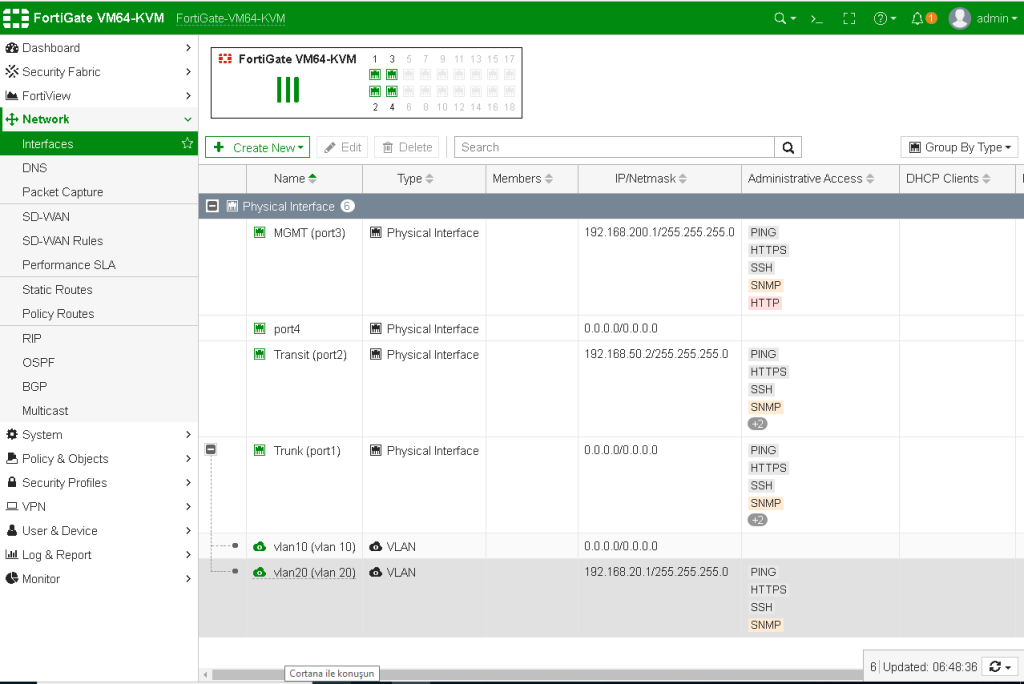
config system interface
edit port2
set alias Transit
set role lan
set mode static
set ip 192.168.50.2 255.255.255.0 // This is the Web GUI access from internal network after conf.
set allowaccess http https ssh ping telnet snmp
next
edit port1
set alias LAN
set role lan
set mode static
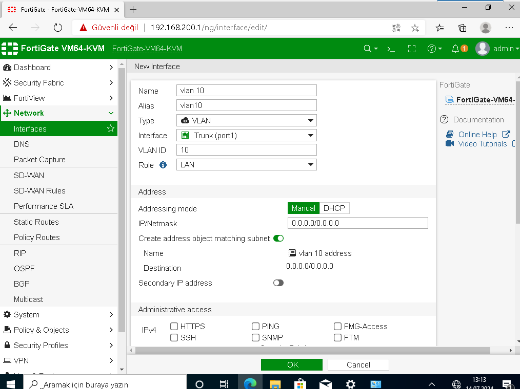
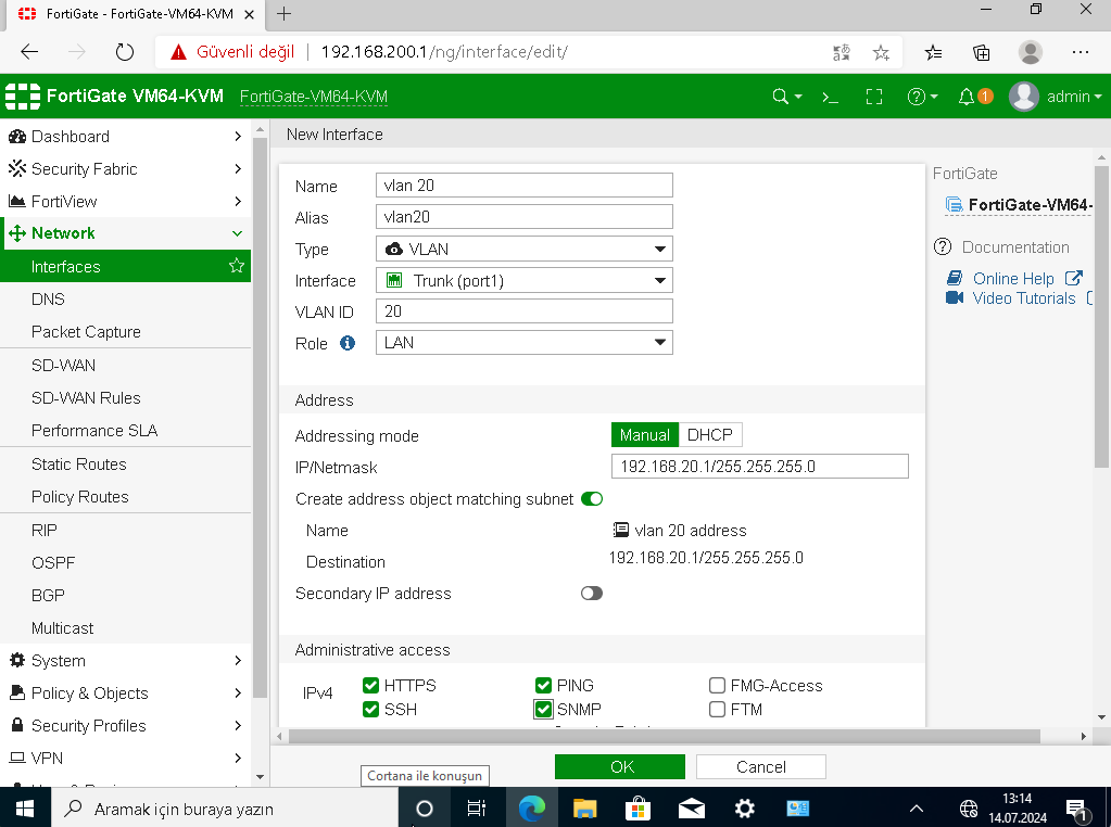
NO IP will be configured here as this is TRUNK port. Also we will create the VLAN 20 interface on this physical interface on Internal firewall later.
set allowaccess http https ssh ping telnet snmp
end
Now carefully inspect the next configurations on internal firewall. Interface settings, static routes, ipv4 policies and VLAN creations.
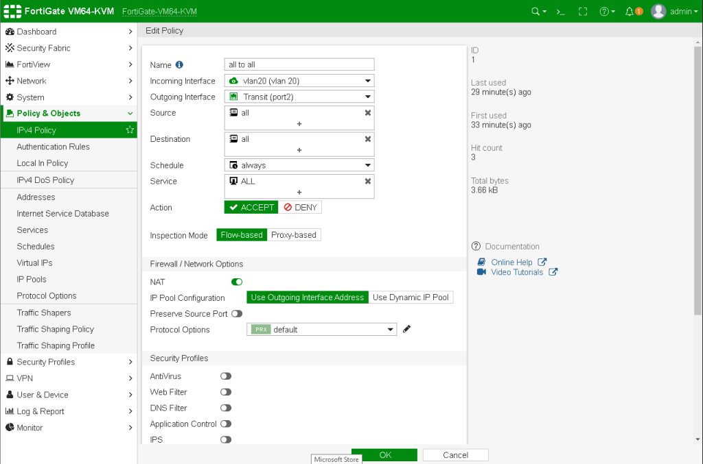
Now disable the windows firewall on all clients and try to ping each devices. You will be able to ping VLAN 20 devices as we permitted all on Internal Firewall IPV4 policies. To set specific access for each devices, create new address for each devices on the firewall as 192.168.20.11/32 then only allow these known devices with desired protocols and services.
Happy networking 🙂 Do not hesitate to contact me for your questions. 🙂