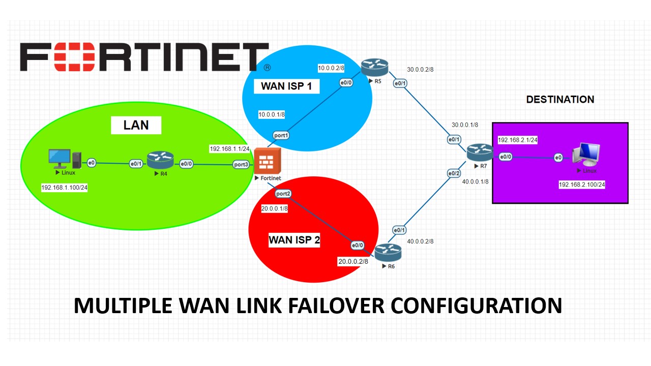
On our topology, we have Fortigate firewall, Cisco routers and 2 ISP provider with 20.0.0.2 and 10.0.0.2 gateways. We would like to setup a basic failover on Fortigate firewall which will allow us to use 2nd ISP link if ISP-1 drops. Basic idea behind this is “administrative distance” on Static routes on the firewall. We will set ISP-1 as 10 and ISP-2 as 20 and firewall will decide from which interface to send out packages. If one of the WAN links drops, the second will continue to propagate the packages automatically.
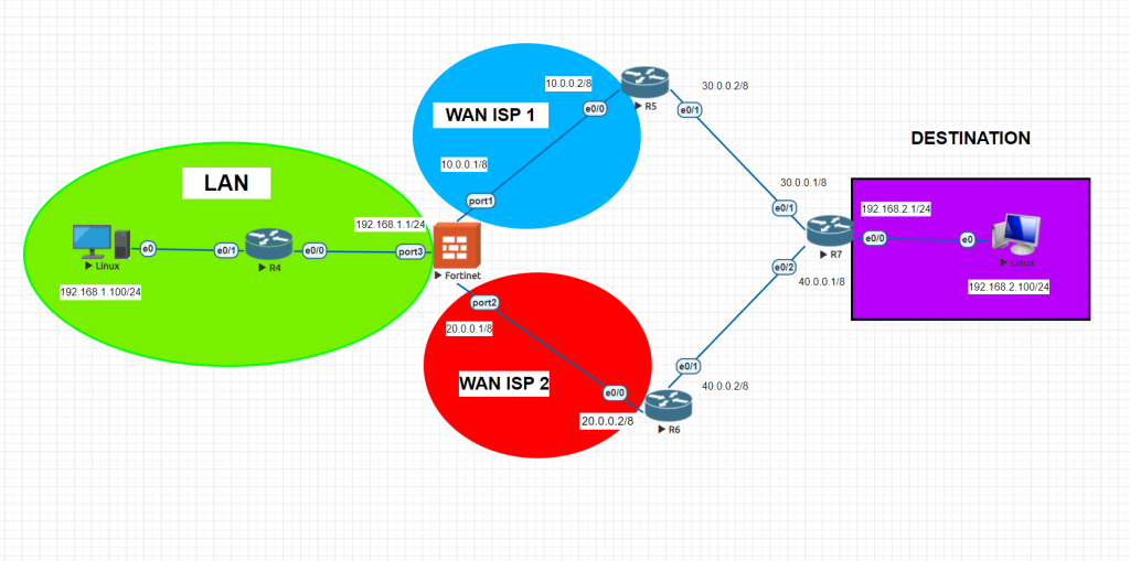
Lets take a look at the LLD of Fortinet interfaces
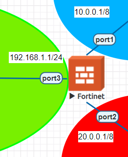
We will start with Fortigate firewall configurations.
config system interface
   edit port1
   set alias WAN1
   set role wan
   set mode static
   set ip 10.0.0.1 255.0.0.0
   set allowaccess http https telnet ping ssh fgfm
    next
   edit port2
   set alias WAN2
   set role wan
   set mode static
   set ip 20.0.0.1 255.0.0.0
   set allowaccess ping ssh telnet http https fgfm
    next
   edit port3
   set alias LAN
   set role lan
   set mode static
   set ip 192.168.1.1 255.255.255.0
   set allowaccess http https telnet ssh ping fgfm
   end
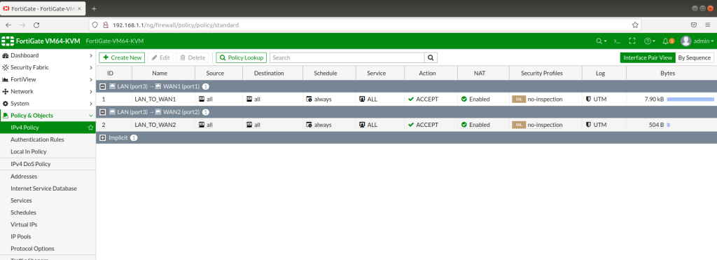
Afterwards, we will connect to Fortigate FW from the 192.168.1.100 client for GUI configurations. As shown below; we will configure Static routes for both 2 ISPs and also we will create 2 static routes for 2 ISPs with connected gateways. Also here, we will set Administrative Cost parameters as 10 and 20 . And firewall will choose the lowest integer which is given on the interfaces and traffic will flow from this interface. Also to be able to use basic services like ICMP etc, we will set IPV4 policies for both interfaces.
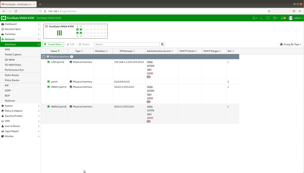
INTERFACE CONFIGURATION CHECK
STATIC ROUTES

IPV4 POLICIES
PINGING DESTINATION 192.168.2.100
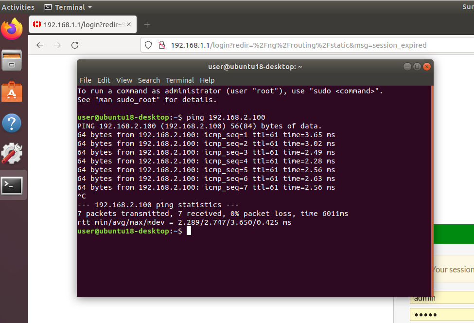
You can also install traceroute package on Ubuntu to trace and test failover configurations. And you will realize that the traffic flow changes if you change administrative cost value or disable one of the ISP WAN links.
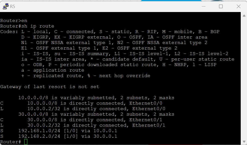
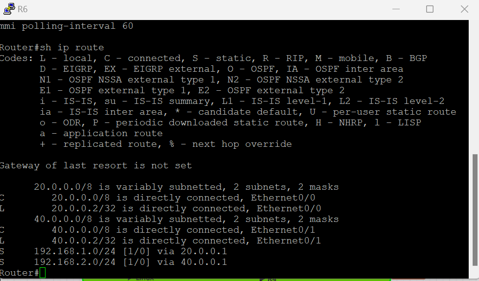
For Cisco Router configurations all you need to do is to set static routes for far routes like below.
CISCO ROUTER STATIC ROUTE CONFIGURATIONS
ROUTER 5
enable
config terminal
int e0/0
ip address 10.0.0.2 255.0.0.0
no shutdown

int e0/1
ip address 30.0.0.2 255.0.0.0
no shutdown

ip route 192.168.1.0 255.255.255.0 10.0.0.1
ip route 192.168.2.0 255.255.255.0 30.0.0.1
ROUTER 6
enable
config terminal
int e0/0
ip address 20.0.0.2 255.0.0.0
no shutdown

int e0/1
ip address 40.0.0.2 255.0.0.0
no shutdown

ip route 192.168.1.0 255.255.255.0 20.0.0.1
ip route 192.168.2.0 255.255.255.0 40.0.0.1
ROUTER 7
enable
config terminal
int e0/0
ip address 192.168.2.1 255.255.255.0
no shutdown

int e0/1
ip address 30.0.0.1 255.0.0.0
no shutdown

int e0/2
ip address 40.0.0.1 255.0.0.0
no shutdown

ip route 10.0.0.0 255.0.0.0 30.0.0.2  (to be able to get 10 network use 30.0.0.2 interface)
ip route 20.0.0.0 255.0.0.0 40.0.0.2  (to be able to get 20 network use 40.0.0.2 interface)
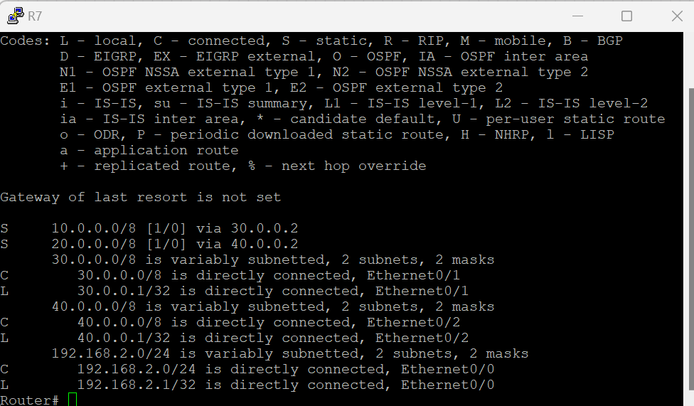
After configuring all the routers, do the ping tests and check the configs static routes.
Also you can ignore this Cisco Router endings if you have set your EVENG network connected to internet. You can directly use 2 cloud network instead of this WAN simulation.
Do not hesitate to contact me if you have further questions.
These configurations are only for educational purposes.
Always use strong passwords and full configurations with original devices.
Happy networking 🙂
