HSRP, or the Hot Standby Router Protocol, is a Cisco proprietary protocol that enables two or more routers to work together in a group to present the illusion of a single virtual router to hosts on a LAN. The main purpose of HSRP is to establish network redundancy and avoid single points of failure, thus ensuring uninterrupted network service.
In an HSRP group, one router is elected as the Active router, and another as the Standby router. The Active router handles all the packet forwarding. If it fails for any reason, the Standby router takes over without disrupting traffic. This is known as a failover. The other routers in the group remain in the Listen state; they receive and process HSRP messages but do not participate in the active routing.
HSRP uses a virtual MAC address and an IP address that is shared among the group. Hosts use this IP address as the default gateway, and the protocol ensures that this IP address is always reachable as long as at least one of the routers in the group is operational.
Key characteristics of HSRP include:
- HSRP operates over UDP and uses port number 1985.
- HSRP version 1 (default version on most routers) allows for up to 256 HSRP groups (0 to 255). HSRP version 2 allows for up to 4096 groups (0 to 4095).
- Preemption is supported, meaning a higher priority router can take over as Active if it comes online after the current Active router.
- HSRP supports tracking, which allows the priority of a router to be adjusted based on the state of its interfaces.
HSRP, while proprietary to Cisco, has a similar functionality to the open-standard Virtual Router Redundancy Protocol (VRRP).
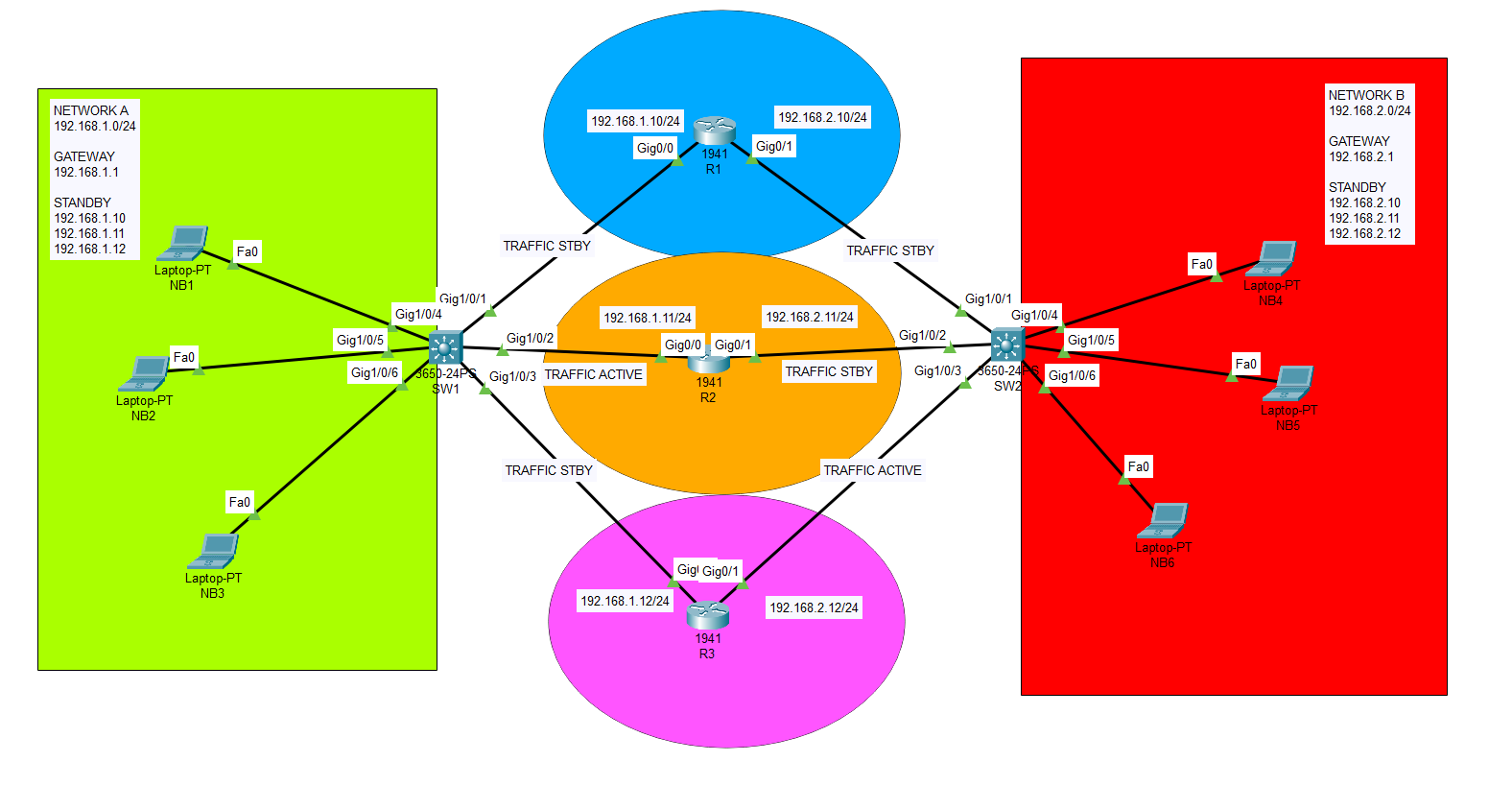
On this topology, 3 routers are in use to present basic implementation of HSRP protocol. There are 2 different gateways for 2 network and these gateways will be presented by a Virtual IP address.. With standby command, we will define both specific IP address and a standby gateway address to each router interface. Network A will be presented as 192.168.1.0/24 and Network B will be presented as 192.168.2.0/24.
At the end of this example, we will examine the traffic routing through routers as we are using HSRP protocol. Also, priority property can be also used to determine the necessity of the routing needs.
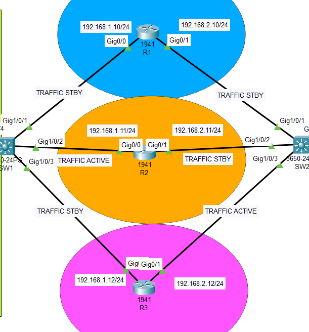
HSRP LOGICAL TOPOLOGY

HSRP LOW LEVEL DIAGRAM
ROUTER 1 CONFIGURATION
Router>enable
Router#configure terminal
Enter configuration commands, one per line.  End with CNTL/Z.
Router(config)#hostname R1
R1(config)#int g0/0
R1(config-if)#ip address 192.168.1.10 255.255.255.0
R1(config-if)#no shutdown
R1(config-if)#standby 1 ip 192.168.1.1
R1(config-if)#exit
R1(config)#int g0/1
R1(config-if)#ip address 192.168.2.10 255.255.255.0
R1(config-if)#no shutdown
R1(config-if)#standby 2 ip 192.168.2.1
R1(config-if)#no shutdown
R1(config-if)#exit
R1(config)#
R1#
%SYS-5-CONFIG_I: Configured from console by console

%HSRP-6-STATECHANGE: GigabitEthernet0/1 Grp 2 state Speak -> Standby

%HSRP-6-STATECHANGE: GigabitEthernet0/1 Grp 2 state Standby -> Active
ROUTER 2 CONFIGURATION
Router(config)#hostname R2
R2(config)#int g0/0
R2(config-if)#ip address 192.168.1.11 255.255.255.0
R2(config-if)#standby 1 ip 192.168.1.1
R2(config-if)#no shutdown
R2(config-if)#exit
R2(config)#int g0/1
R2(config-if)#ip address 192.168.2.11 255.255.255.0
R2(config-if)#standby 2 ip 192.168.2.1
R2(config-if)#no shutdown
R2(config-if)#exit
R2(config)#do wr
Building configuration...
[OK]
R2(config)#
%HSRP-6-STATECHANGE: GigabitEthernet0/1 Grp 2 state Speak -> Standby

%HSRP-6-STATECHANGE: GigabitEthernet0/1 Grp 2 state Standby -> Active
ROUTER 3 CONFIGURATION
Router#configure terminal
Enter configuration commands, one per line.  End with CNTL/Z.
Router(config)#hostname R3
R3(config)#int g0/0
R3(config-if)#ip address 192.168.1.12 255.255.255.0
R3(config-if)#standby 2 ip 192.168.1.1
R3(config-if)#no shutdown
R3(config-if)#exit
R3(config)#int g0/1
R3(config-if)#ip address 192.168.2.12 255.255.255.0
R3(config-if)#standby 2 ip 192.168.2.1
R3(config-if)#no shutdown
R3(config-if)#exit
R3(config)#
%HSRP-6-STATECHANGE: GigabitEthernet0/1 Grp 2 state Speak -> Standby

%HSRP-6-STATECHANGE: GigabitEthernet0/1 Grp 2 state Standby -> Active
DISPLAY ALL ACTIVE-STANDBY ROUTES
R1#show standby
GigabitEthernet0/0 – Group 1
State is Standby
6 state changes, last state change 00:00:58
Virtual IP address is 192.168.1.1
Active virtual MAC address is 0000.0C07.AC01
Local virtual MAC address is 0000.0C07.AC01 (v1 default)
Hello time 3 sec, hold time 10 sec
Next hello sent in 0.255 secs
Preemption disabled
Active router is 192.168.1.11
Standby router is local
Priority 100 (default 100)
Group name is hsrp-Gig0/0-1 (default)
GigabitEthernet0/1 – Group 2
State is Listen
7 state changes, last state change 00:01:05
Virtual IP address is 192.168.2.1
Active virtual MAC address is 0000.0C07.AC02
Local virtual MAC address is 0000.0C07.AC02 (v1 default)
Hello time 3 sec, hold time 10 sec
Next hello sent in 0 secs
Preemption disabled
Active router is 192.168.2.12
Standby router is 192.168.2.11
Priority 100 (default 100)
Group name is hsrp-Gig0/1-2 (default)
TRACEROUTE FROM PC 1 TO PC 4
C:\>tracert 192.168.2.70

Tracing route to 192.168.2.70 over a maximum of 30 hops:

  1   *         0 ms      0 ms      192.168.1.11
  2   *         *         0 ms      192.168.2.70

Trace complete.

C:\>
TRACEROUTE FROM PC 4 TO PC 1
C:\>tracert 192.168.1.50

Tracing route to 192.168.1.50 over a maximum of 30 hops:

  1   0 ms      0 ms      0 ms      192.168.2.12
  2   0 ms      0 ms      0 ms      192.168.1.50

Trace complete.

C:\>
You can also download this simulation below…
Feel free to contact me if you have any further question regarding this topology.
Happy networking :))