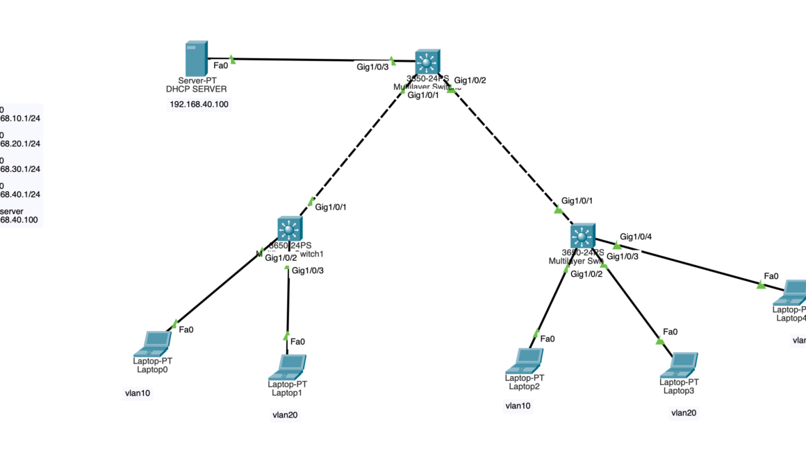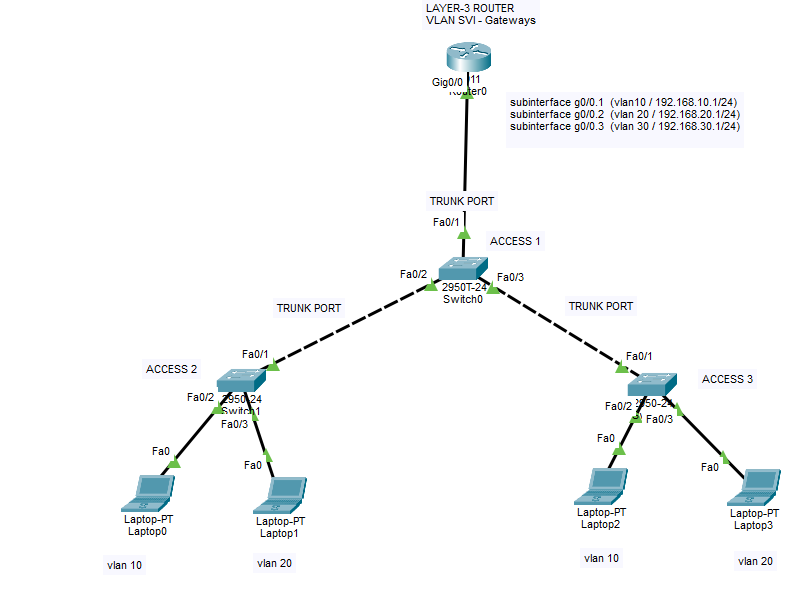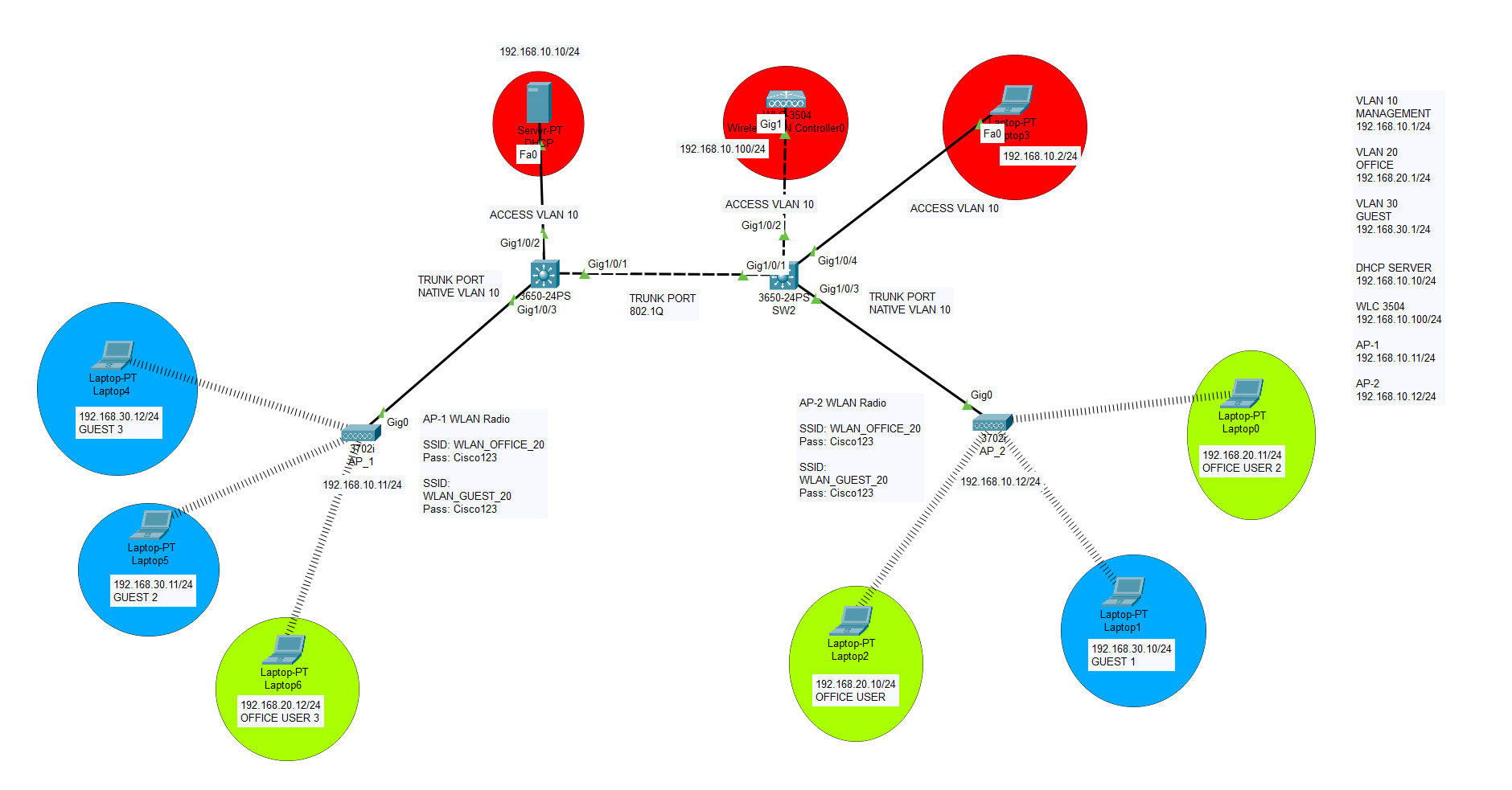
Let’s start configuring our VLANs and ports. We will create 3 VLANs on SW1 core switch. One of them will serve as Management subnet, others will serve as Office and Guest networks. Upon completion of VLAN and port configurations, we will start configuring Cisco Wireless Controllers and our Cisco Access Points. Both access points will be connected to one controller and will propagate multiple radio SSIDs which will be connected to different VLANs. So at the end, our end-users will be able to receive IP address from their own DHCP scopes using 802.1Q protocol through different SSIDs. I will also add my Cisco Packet Tracer simulation configuration file at the end, so you can download and inspect for your own training !
During the training our SSID passwords will be easy to remember : Cisco123
Wireless controller GUI username will be : admin and password will be : Cisco123
So please be advised, do not use these unsecure passwords in your real environment 🙂

Let’s start with VLANs and port configurations first.
SWITCH 1

Switch#configure terminal
Enter configuration commands, one per line.  End with CNTL/Z.
Switch(config)#hostname SW1
SW1(config)#vlan 10
SW1(config-vlan)#vlan 20
SW1(config-vlan)#vlan 30
SW1(config-vlan)#exit
SW1(config)#interface vlan 10
SW1(config-if)#
%LINK-5-CHANGED: Interface Vlan10, changed state to up

SW1(config-if)#description MANAGEMENT
SW1(config-if)#ip address 192.168.10.1 255.255.255.0
SW1(config-if)#ip helper-address 192.168.10.10
SW1(config-if)#no shutdown
SW1(config-if)#exit
SW1(config)#interface vlan 20
SW1(config-if)#
%LINK-5-CHANGED: Interface Vlan20, changed state to up

SW1(config-if)#description OFFICE
SW1(config-if)#ip address 192.168.20.1 255.255.255.0
SW1(config-if)#ip helper-address 192.168.10.10
SW1(config-if)#no shutdown
SW1(config-if)#exit
SW1(config)#interface vlan 30
SW1(config-if)#
%LINK-5-CHANGED: Interface Vlan30, changed state to up

SW1(config-if)#description GUEST
SW1(config-if)#ip address 192.168.30.1 255.255.255.0
SW1(config-if)#ip helper-address 192.168.10.10
SW1(config-if)#no shutdown
SW1(config-if)#exit
SW1(config)#do wr
Building configuration...
Compressed configuration from 7383 bytes to 3601 bytes[OK]
[OK]
SW1(config)#ip routing
SW1(config)#int g1/0/1
SW1(config-if)#sw mode trunk

SW1(config-if)#
%LINEPROTO-5-UPDOWN: Line protocol on Interface GigabitEthernet1/0/1, changed state to down

%LINEPROTO-5-UPDOWN: Line protocol on Interface GigabitEthernet1/0/1, changed state to up

%LINEPROTO-5-UPDOWN: Line protocol on Interface Vlan10, changed state to up

%LINEPROTO-5-UPDOWN: Line protocol on Interface Vlan20, changed state to up

%LINEPROTO-5-UPDOWN: Line protocol on Interface Vlan30, changed state to up

SW1(config-if)#switchport trunk native vlan 10
SW1(config-if)#no shutdown
SW1(config-if)#exit
SW1(config)#do wr
Building configuration...
Compressed configuration from 7383 bytes to 3601 bytes[OK]
[OK]
SW1(config)#
SW1(config)#
SW1(config)#interface g1/0/2
SW1(config-if)#switchport mode acc
SW1(config-if)#switchport access vlan 10
SW1(config-if)#no shutdown
SW1(config-if)#exit
SW1(config)#int g1/0/3
SW1(config-if)#switchport mode trunk

SW1(config-if)#
%LINEPROTO-5-UPDOWN: Line protocol on Interface GigabitEthernet1/0/3, changed state to down

%LINEPROTO-5-UPDOWN: Line protocol on Interface GigabitEthernet1/0/3, changed state to up

SW1(config-if)#switchport trunk native vlan 10
SW1(config-if)#no shutdown
SW1(config-if)#exit
SW1(config)#
SW1#
%SYS-5-CONFIG_I: Configured from console by console
SWITCH-2
It is time to configure Cisco Core switch 2.
Switch>en
Switch#conf t
Enter configuration commands, one per line. End with CNTL/Z.
Switch(config)#hostname SW2
SW2(config)#interface g1/0/1
SW2(config-if)#switchport mode trunk
SW2(config-if)#switchport trunk native vlan 10
SW2(config)#interface g1/0/1
SW2(config-if)#no shutdown
SW2(config-if)#exit
SW2(config)#do wr
Building configuration…
Compressed configuration from 7383 bytes to 3601 bytes[OK]
[OK]
SW2(config)#interface g1/0/2
SW2(config-if)#switchport mode trunk
SW2(config-if)#
%LINEPROTO-5-UPDOWN: Line protocol on Interface GigabitEthernet1/0/2, changed state to down
%LINEPROTO-5-UPDOWN: Line protocol on Interface GigabitEthernet1/0/2, changed state to up
SW2(config-if)#switchport trunk native vlan 10
SW2(config-if)#no shutdown
SW2(config-if)#exit
SW2(config)#interface g1/0/3
SW2(config-if)#switchport mode trunk
SW2(config-if)#
%LINEPROTO-5-UPDOWN: Line protocol on Interface GigabitEthernet1/0/3, changed state to down
%LINEPROTO-5-UPDOWN: Line protocol on Interface GigabitEthernet1/0/3, changed state to up
SW2(config-if)#switchport trunk native vlan 10
SW2(config-if)#no shutdown
SW2(config-if)#exit
SW2(config)#vlan 10
SW2(config-vlan)#vlan 20
SW2(config-vlan)#vlan 30
SW2(config-vlan)#exit
SW2(config)#
SW2(config)#do wr
Building configuration…
Compressed configuration from 7383 bytes to 3601 bytes[OK]
[OK]
SW2(config)#exit
SW2#
%SYS-5-CONFIG_I: Configured from console by console
SW2#copy running-config startup-config
Destination filename [startup-config]?
Building configuration…
[OK]
SW2#
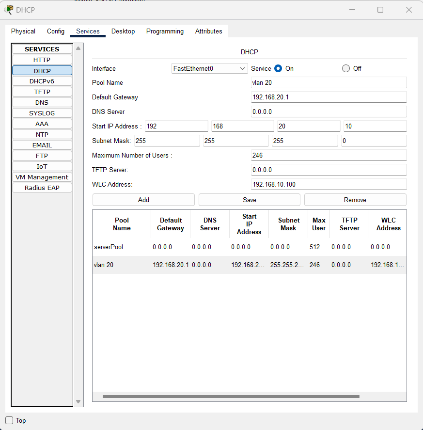
Create all VLAN DHCP scopes on DHCP server, only except for Management VLAN. Because we plan to use Management subnet with manually assigned IPs.
CISCO WIRELESS CONTROLLER CONFIGURATIONS
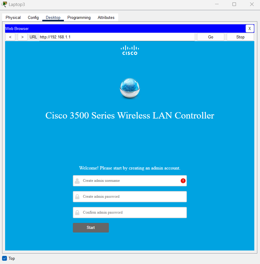
At the first phase, directly connect your PC to Wireless controller to access it. Define an IP address from the same subnet of WLC to your PC. After completing WLC configuration, you may directly connect your PC to core switch to receive an IP address from Management Network. Create a user at the first phase, do not panic; it takes a long time to load the page on the browser. Make sure you try with HTTPS protocol at the next phase if it doesn’t connect. Also some regional settings are not possible for example changing “country”.
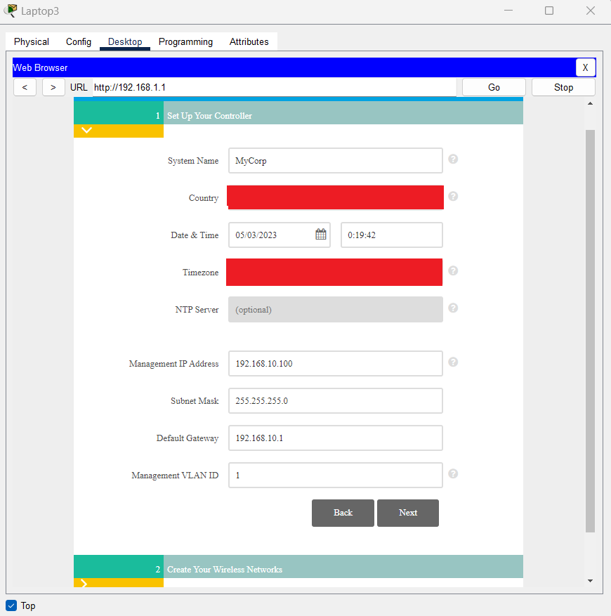
Complete the basic initial setup of WLC with following details and do not assign Management VLAN ID as you created on Core switch, it should be VLAN ID : 1
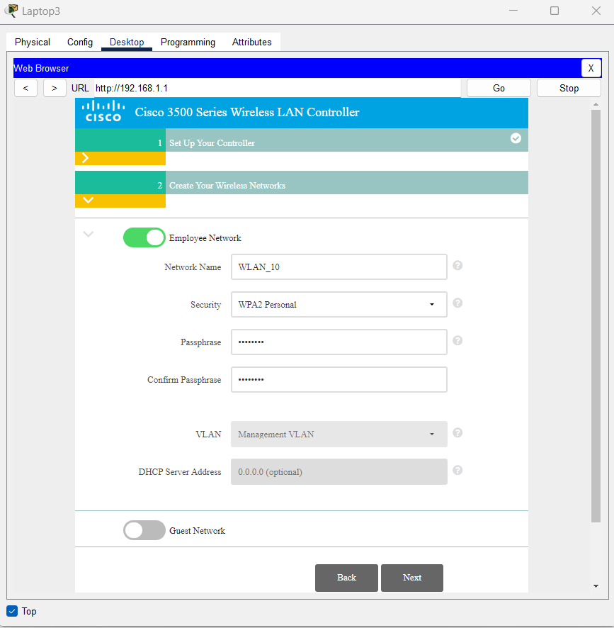
For now choose Employee network, afterwards we will configure them. To proceed you need to choose this option as enabled.
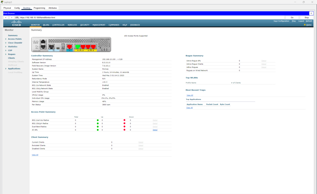
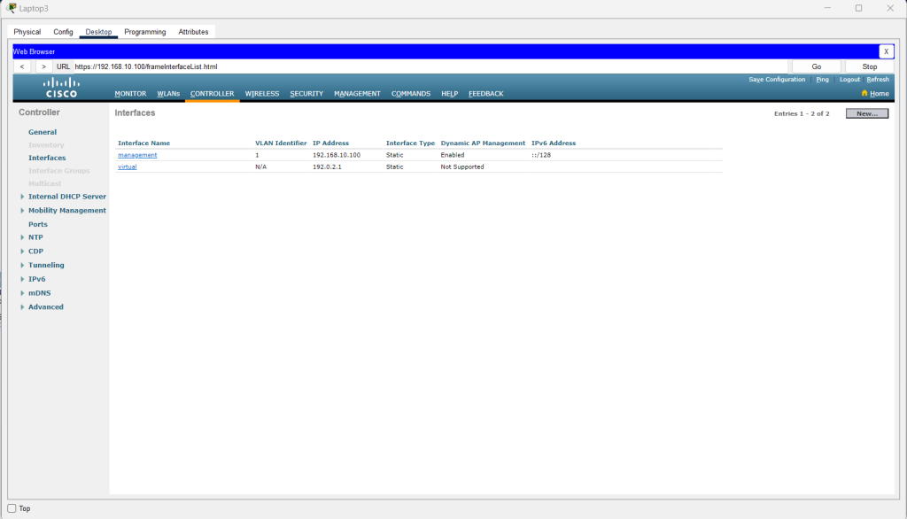
Here is the general dashboard of our Cisco Wireless Controller
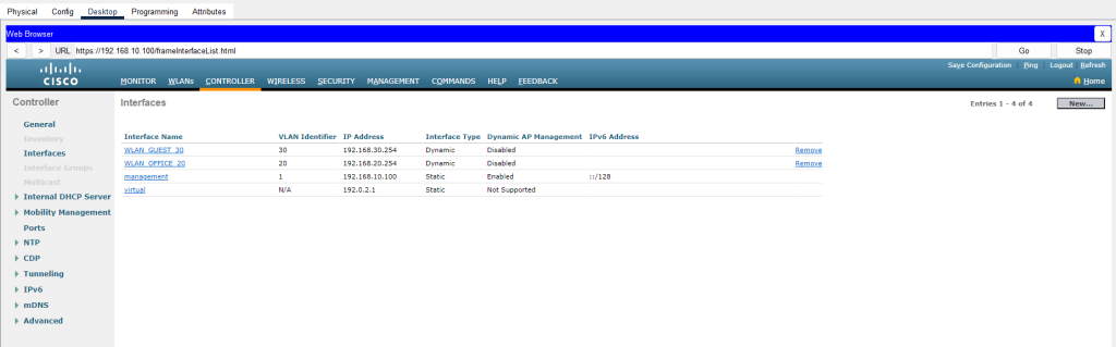
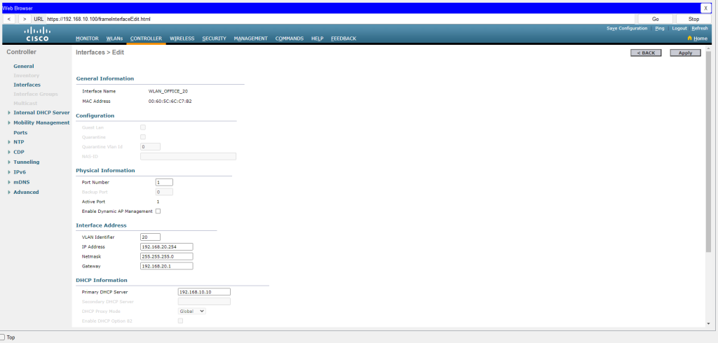
Configure all the interfaces on the WLC. All the VLAN data already have been carried to WLC with our Trunk ports. So define related VLAN IDs to interfaces and implement the network – subnet informations here seperately on all VLANs.
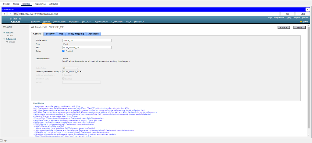
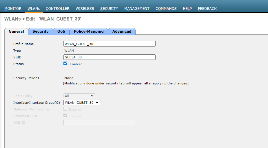
Afterwards, at the next phase we need to create WLANs to determine our SSID properties. As we mentioned APs will propagate different SSIDs for each VLANs so we need to create 2 different SSIDs with different VLAN IDs. Make sure that you choose the “Enabled” option and choose the right interface according to VLAN itself.
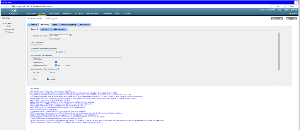
From the security tab, enable below options or you may choose different security policies rather than WPA + WPA2 and preshared key (PSK). And at this phase you need to define a password for SSIDs.
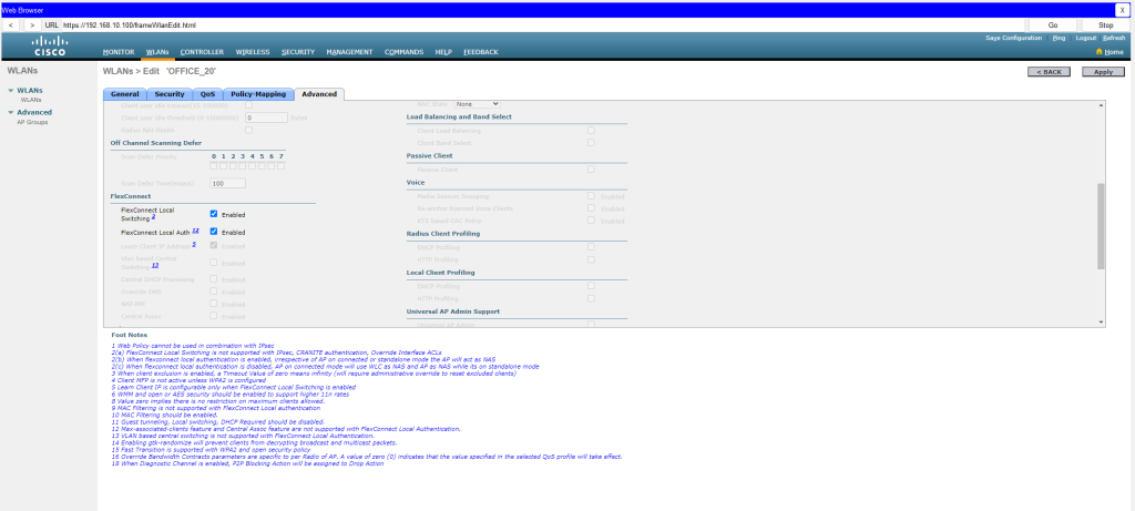
Enable Flexconnect options for CAPWAP tunnel etc.
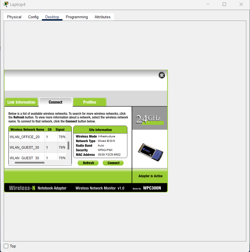
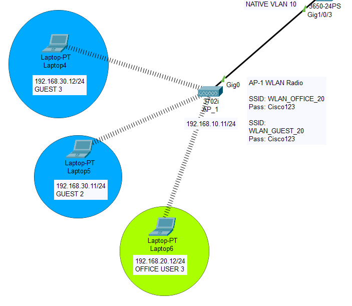
Before you connect to wireless network, we need to configure our PCs network hardware. Go to PC’s hardware configuration and choose the first wireless network card from the collection. Then turn on the device, then from the desktop menu choose “PC Wireless” application. Once you refresh the WLAN list, you will discover there are 4 SSIDs available 2 for Guests, 2 for Office. Don’t be surprised, you have done everything right, the reason is; your PC also receives SSID radio signals from second AP as well. Signal strenght can be adjusted later to prevent signal distortion. At this phase connect to a wireless network, check your connectivity with other devices. Also check your private IP to make sure that you have completed every step correctly.
KEY POINTS FOR THIS IMPLEMENTATION (Things to consider)
1- Do not forget to check WLC GUI interface to assign manual private IP
2- Do not forget to check AP GUI interface to assign manual private IP, also assign WLC IP here to make APs easy to access WLC directly. Otherwise APs won’t be discovered on your WLC GUI. In real environment, you may be required to use determine 43th section rule on DHCP Scope settings. On 43th section, you are required to assign an ASCII according to vendor’s properties but not needed on this environment.
3- Do not forget to assign “TRUNK NATIVE VLANs”. Assigning trunk ports doesn’t mean that your WLC or APs can communicate with other devices, do not forget this step, it is critical.
4- Do not forget to set “ip routing” command to enable intervlan routing on core switches. It is a very easy command. In case you miss it, you may stuck with troubleshooting even it is a very easy command.
5- Also another topologies are possible. On this training, I created VLANs on Cisco Core switches. You may create Guest network SVI on WLC or you may want to create isolated second DHCP server. Or even you might want to define different gateways, these are all possible fantasies.
Please do not hesitate to contact me regarding your questions.
Happy networking!! 🙂
Here is my packet tracer simulation link below for you;