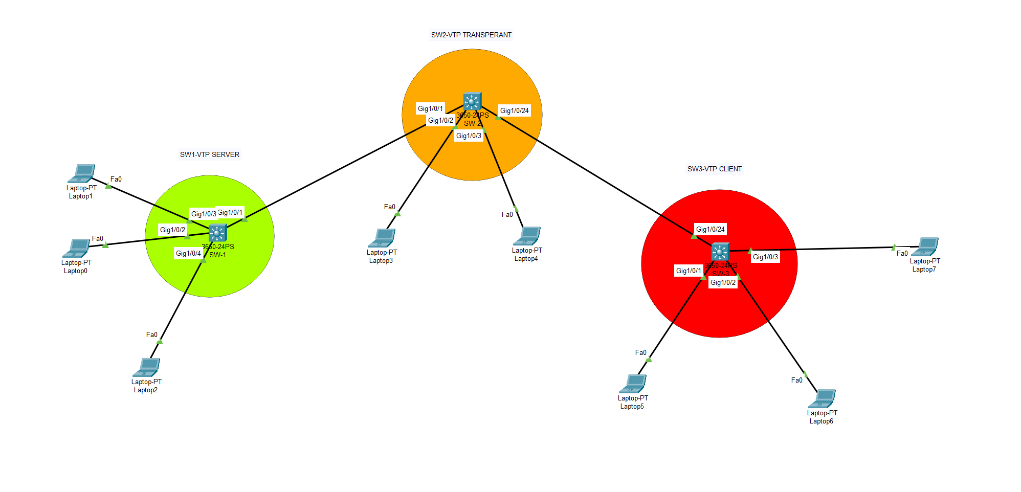
A VTP server is a switch to which other switches are connected.
The VTP server maintains the VLAN database and propagates it to all the other switches.
There are three modes in which a VTP server can operate: Server, Client and Transparent.
The Server mode is used when there is more than one switch in an environment where they need to share the same VLANs.
The Client mode is used for smaller networks with only one switch, where that switch needs to be able to communicate with other switches but does not need to share any information about its database with them.
The Transparent mode allows a switch that does not have any configured VLANs of its own and has no database of its own, so it will take on whatever database is sent from the nearest active server or client.
IMPORTANT ! : VTP protocol is only used with Cisco switches.
In order for the VTP configuration on the switches to work, the VTP domain and VTP password information must be the same for all switches.
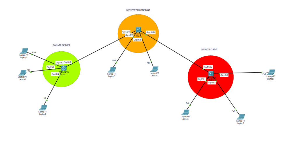
Let’s start with the first switch configuration. Our first switch will be configured as VTP server mode.
SW1(config)#interface GigabitEthernet1/0/1
SW1(config-if)#switchport trunk encapsulation dot1q
SW1(config-if)#switchport mode trunk

SW1#

SW2(config)#interface GigabitEthernet1/0/1
SW2(config-if)#switchport trunk encapsulation dot1q
SW2(config-if)#switchport mode trunk
SW2#
SW2(config)#interface GigabitEthernet1/0/24
SW2(config-if)#switchport trunk encapsulation dot1q
SW2(config-if)#switchport mode trunk
SW2#


SW3(config)#interface GigabitEthernet1/0/24
SW3(config-if)#switchport trunk encapsulation dot1q
SW3(config-if)#switchport mode trunk
SW3#


SW1(config)#vtp domain ITOPS
Changing VTP domain name from NULL to ITOPS
SW1(config)#vtp password baris123.
Setting device VLAN database password to baris123.
SW1(config)#vtp mode server
Device mode already VTP SERVER.
SW1(config)#vtp version 2
SW1(config)#do wr
SW1#
Second switch (SW2) will be prepared as VTP Transparent mode.
Switch>enable
Switch#configure terminal
Enter configuration commands, one per line.  End with CNTL/Z.
Switch(config)#hostname SW2

SW2(config)#vtp domain ITOPS
Changing VTP domain name from NULL to ITOPS
SW2(config)#vtp password baris123.
Setting device VLAN database password to baris123.
SW2(config)#vtp mode transparent
Setting device to VTP TRANSPARENT mode.
SW2(config)#vtp version 2
SW2(config)#do wr
Building configuration...
Compressed configuration from 7383 bytes to 3601 bytes[OK]
[OK]
SW2(config)#
SW2#
And our 3rd switch will be configured as VTP client mode.
Switch>enable
Switch#configure terminal
Enter configuration commands, one per line.  End with CNTL/Z.
Switch(config)#hostname SW3

SW3(config)#vtp domain ITOPS
Changing VTP domain name from NULL to ITOPS
SW3(config)#vtp password baris123.
Setting device VLAN database password to baris123.
SW3(config)#vtp mode client
Setting device to VTP CLIENT mode.
SW3(config)#do wr
Building configuration...
Compressed configuration from 7383 bytes to 3601 bytes[OK]
[OK]
SW3(config)#
Time to create VLANs,
Switch>enable
Switch#configure terminal
Enter configuration commands, one per line.  End with CNTL/Z.
Switch(config)#hostname SW1
SW1(config)#vlan 10
SW1(config-vlan)#vlan 20
SW1(config-vlan)#vlan 30
SW1(config-vlan)#exit
SW1(config)#do wr
Now we will check VLAN databases on switches. Then we will try to create new VLANs on different modes. VTP server and VTP transparent will be able to create new VLANs but VTP client will fail to create new VLANs.
SWITCH – 1
SW1#show vlan

VLAN Name                             Status    Ports
---- -------------------------------- --------- -------------------------------
1    default                          active    Gig1/0/2, Gig1/0/3, Gig1/0/4, Gig1/0/5
                                                Gig1/0/6, Gig1/0/7, Gig1/0/8, Gig1/0/9
                                                Gig1/0/10, Gig1/0/11, Gig1/0/12, Gig1/0/13
                                                Gig1/0/14, Gig1/0/15, Gig1/0/16, Gig1/0/17
                                                Gig1/0/18, Gig1/0/19, Gig1/0/20, Gig1/0/21
                                                Gig1/0/22, Gig1/0/23, Gig1/0/24, Gig1/1/1
                                                Gig1/1/2, Gig1/1/3, Gig1/1/4
10   VLAN0010                         active
20   VLAN0020                         active
30   VLAN0030                         active
1002 fddi-default                     active
1003 token-ring-default               active
1004 fddinet-default                  active
1005 trnet-default                    active

VLAN Type  SAID       MTU   Parent RingNo BridgeNo Stp  BrdgMode Trans1 Trans2
---- ----- ---------- ----- ------ ------ -------- ---- -------- ------ ------
1    enet  100001     1500  -      -      -        -    -        0      0
10   enet  100010     1500  -      -      -        -    -        0      0
 --More--
SW1#sh vtp status
VTP Version capable : 1 to 2
VTP version running : 2
VTP Domain Name : ITOPS
VTP Pruning Mode : Disabled
VTP Traps Generation : Disabled
Device ID : 0001.C769.8600
Configuration last modified by 0.0.0.0 at 3-1-93 00:10:41
Local updater ID is 0.0.0.0 (no valid interface found)
Feature VLAN :
--------------
VTP Operating Mode : Server
Maximum VLANs supported locally : 1005
Number of existing VLANs : 8
Configuration Revision : 3
MD5 digest : 0x08 0xF1 0x8B 0xC0 0x36 0x17 0x28 0xF4
0xAD 0xDA 0x74 0x60 0xCB 0xA2 0x18 0xB8 SWITCH – 2
We can create new VLANs here. And it is possible to check and see the status of current VLANs.
SWITCH – 3
SW3#sh vlan

VLAN Name                             Status    Ports
---- -------------------------------- --------- -------------------------------
1    default                          active    Gig1/0/1, Gig1/0/2, Gig1/0/3, Gig1/0/4
                                                Gig1/0/5, Gig1/0/6, Gig1/0/7, Gig1/0/8
                                                Gig1/0/9, Gig1/0/10, Gig1/0/11, Gig1/0/12
                                                Gig1/0/13, Gig1/0/14, Gig1/0/15, Gig1/0/16
                                                Gig1/0/17, Gig1/0/18, Gig1/0/19, Gig1/0/20
                                                Gig1/0/21, Gig1/0/22, Gig1/0/23, Gig1/1/1
                                                Gig1/1/2, Gig1/1/3, Gig1/1/4
10   VLAN0010                         active
20   VLAN0020                         active
30   VLAN0030                         active
1002 fddi-default                     active
1003 token-ring-default               active
1004 fddinet-default                  active
1005 trnet-default                    active

VLAN Type  SAID       MTU   Parent RingNo BridgeNo Stp  BrdgMode Trans1 Trans2
---- ----- ---------- ----- ------ ------ -------- ---- -------- ------ ------
1    enet  100001     1500  -      -      -        -    -        0      0
10   enet  100010     1500  -      -      -        -    -        0      0
SW3(config)#vlan 40
VTP VLAN configuration not allowed when device is in CLIENT mode.
IMPORTANT : It is not possible to create new VLANs on VTP client mode. But current VLANs which created on VTP Server switch will be seen on these switches.