In this lab, we will inspect how intervlan communication handled on Layer-3 Router with Router On a Stick model. If you have layer 2 switches for end devices, then you will need a layer 3 router or switch for intervlan communication. Layer 2 devices cannot do IP routing between VLAN gateways (SVIs) so therefore you will need to collect and divert all the traffic to a decision maker (IP routing capable device). In our scenerio we have 3 switches where 2 of them are used for end user devices and connected to ACCESS 1 switch with trunk mode. Then we use fa0/1 as trunk port on ACCESS 1 switch. On Router g0/0 port, we use this 1 physical cable as trunk connection but we need to use “subinterfaces” to create virtual interfaces to forward the traffic to router. This is mainly needed to create a VLAN interface on Router side. You cannot create VLAN SVIs (gateways) on layer 2 devices as they dont have IP routing capabilities. All the network traffic will end on router because all vlan gateways are created on the router. Then we will use access switches with their Layer 2 vlan capabilities to connect the devices.
Below you can see our basic topology. I intentionally kept it simple so you can easily understand the main configurations.
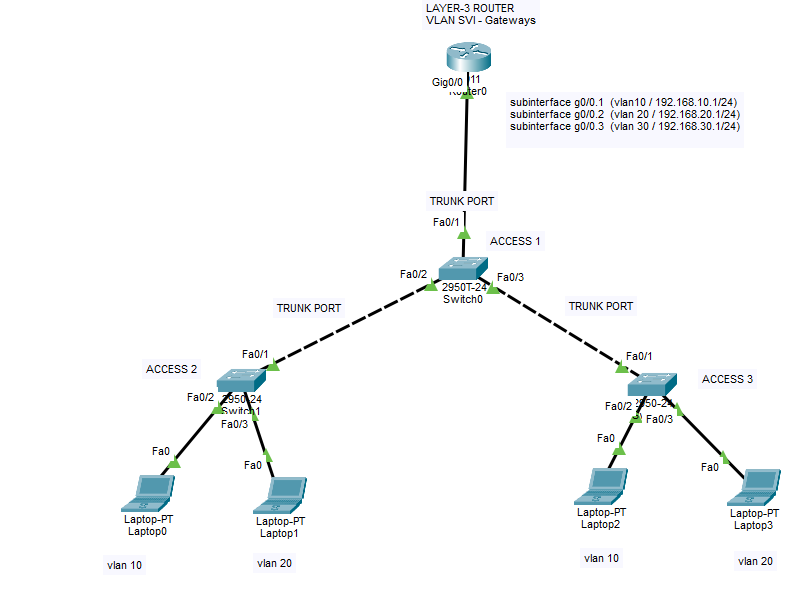
We will have 3 VLANS as below;
VLAN 10 – 192.168.10.1/255.255.255.0
VLAN 20 – 192.168.20.1/255.255.255.0
VLAN 30 – 192.168.30.1/255.255.255.0
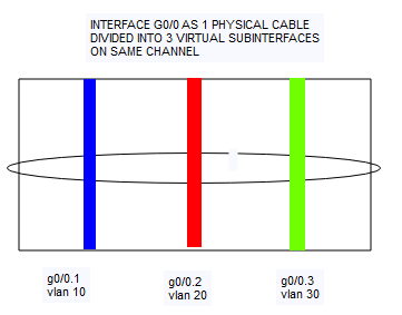
In this below picture, you can understand the logic of this virtual interfaces. As mentioned, we will use 1 physical cable with 3 virtual subinterfaces. There are some disadvantages for this method as well. One of the biggest problem is possible the bottleneck for your internal data transfer bandwidth. If you have to use this method due to your layer 2 devices, try to use this method with fiber connection if you have available fiber ports. Also you can use etherchannel function (LACP protocol) to increase the bandwidth with multiple cables.
Here below you can find the Show Running Configuration Outputs of all switch and routers.
CISCO L3 ROUTER CONFIGURATIONS:
Router>en
Router#conf t
Enter configuration commands, one per line. End with CNTL/Z.
Router(config)#int g0/0
Router(config-if)#int g0/0.1
Router(config-subif)#encapsulation dot1q 10
Router(config-subif)#ip addres 192.168.10.1 255.255.255.0
Router(config-subif)#no sh
Router(config-subif)#int g0/0.2
Router(config-subif)#encapsulation dot1q 20
Router(config-subif)#ip address 192.168.20.1 255.255.255.0
Router(config-subif)#no sh
Router(config-subif)#int g0/0.3
Router(config-subif)#encapsulation dot1q 30
Router(config-subif)#ip address 192.168.30.1 255.255.255.0
Router(config-subif)#no sh
Router(config-subif)#ex
Router(config)#int g0/0
Router(config-if)#no sh
Router(config-if)#
%LINK-5-CHANGED: Interface GigabitEthernet0/0, changed state to up
%LINEPROTO-5-UPDOWN: Line protocol on Interface GigabitEthernet0/0, changed state to up
%LINK-3-UPDOWN: Interface GigabitEthernet0/0.1, changed state to down
%LINEPROTO-5-UPDOWN: Line protocol on Interface GigabitEthernet0/0.1, changed state to up
%LINK-3-UPDOWN: Interface GigabitEthernet0/0.2, changed state to down
%LINEPROTO-5-UPDOWN: Line protocol on Interface GigabitEthernet0/0.2, changed state to up
%LINK-3-UPDOWN: Interface GigabitEthernet0/0.3, changed state to down
%LINEPROTO-5-UPDOWN: Line protocol on Interface GigabitEthernet0/0.3, changed state to up
CREATE LAYER 2 VLANS ON ALL SWITCHES (ONLY VLAN IDs, no gateways yet.)
CREATE Layer 2 VLANS on all switches with below commands
Switch>enable
Switch#configure terminal
Enter configuration commands, one per line. End with CNTL/Z.
Switch(config)#vlan 10
Switch(config-vlan)#vlan 20
Switch(config-vlan)#vlan 30
Switch(config-vlan)#exit
ACCESS SWITCH CONFIGURATION 1
Switch#sh run
Building configuration…
Current configuration : 1149 bytes
!
version 12.1
no service timestamps log datetime msec
no service timestamps debug datetime msec
no service password-encryption
!
hostname Switch
!
!
!
!
!
!
spanning-tree mode pvst
spanning-tree extend system-id
!
interface FastEthernet0/1
switchport mode trunk
!
interface FastEthernet0/2
switchport mode trunk
!
interface FastEthernet0/3
switchport mode trunk
!
interface FastEthernet0/4
!
interface FastEthernet0/5
!
interface FastEthernet0/6
!
interface FastEthernet0/7
!
interface FastEthernet0/8
!
interface FastEthernet0/9
!
interface FastEthernet0/10
!
interface FastEthernet0/11
!
interface FastEthernet0/12
!
interface FastEthernet0/13
!
interface FastEthernet0/14
!
interface FastEthernet0/15
!
interface FastEthernet0/16
!
interface FastEthernet0/17
!
interface FastEthernet0/18
!
interface FastEthernet0/19
!
interface FastEthernet0/20
!
interface FastEthernet0/21
!
interface FastEthernet0/22
!
interface FastEthernet0/23
!
interface FastEthernet0/24
!
interface GigabitEthernet0/1
!
interface GigabitEthernet0/2
!
interface Vlan1
no ip address
shutdown
!
!
!
!
line con 0
!
line vty 0 4
login
line vty 5 15
login
!
!
!
!
end
ACCESS SWITCH CONFIGURATION 2
Switch#sh run
Building configuration…
Current configuration : 1120 bytes
!
version 12.1
no service timestamps log datetime msec
no service timestamps debug datetime msec
no service password-encryption
!
hostname Switch
!
!
!
!
!
!
spanning-tree mode pvst
spanning-tree extend system-id
!
interface FastEthernet0/1
!
interface FastEthernet0/2
switchport access vlan 10
switchport mode access
!
interface FastEthernet0/3
switchport access vlan 20
switchport mode access
!
interface FastEthernet0/4
!
interface FastEthernet0/5
!
interface FastEthernet0/6
!
interface FastEthernet0/7
!
interface FastEthernet0/8
!
interface FastEthernet0/9
!
interface FastEthernet0/10
!
interface FastEthernet0/11
!
interface FastEthernet0/12
!
interface FastEthernet0/13
!
interface FastEthernet0/14
!
interface FastEthernet0/15
!
interface FastEthernet0/16
!
interface FastEthernet0/17
!
interface FastEthernet0/18
!
interface FastEthernet0/19
!
interface FastEthernet0/20
!
interface FastEthernet0/21
!
interface FastEthernet0/22
!
interface FastEthernet0/23
!
interface FastEthernet0/24
!
interface Vlan1
no ip address
shutdown
!
!
!
!
line con 0
!
line vty 0 4
login
line vty 5 15
login
!
!
!
!
end
ACCESS SWITCH CONFIGURATION 3
Switch#show run
Building configuration…
Current configuration : 1143 bytes
!
version 12.1
no service timestamps log datetime msec
no service timestamps debug datetime msec
no service password-encryption
!
hostname Switch
!
!
!
!
!
!
spanning-tree mode pvst
spanning-tree extend system-id
!
interface FastEthernet0/1
switchport mode trunk
!
interface FastEthernet0/2
switchport access vlan 10
switchport mode access
!
interface FastEthernet0/3
switchport access vlan 20
switchport mode access
!
interface FastEthernet0/4
!
interface FastEthernet0/5
!
interface FastEthernet0/6
!
interface FastEthernet0/7
!
interface FastEthernet0/8
!
interface FastEthernet0/9
!
interface FastEthernet0/10
!
interface FastEthernet0/11
!
interface FastEthernet0/12
!
interface FastEthernet0/13
!
interface FastEthernet0/14
!
interface FastEthernet0/15
!
interface FastEthernet0/16
!
interface FastEthernet0/17
!
interface FastEthernet0/18
!
interface FastEthernet0/19
!
interface FastEthernet0/20
!
interface FastEthernet0/21
!
interface FastEthernet0/22
!
interface FastEthernet0/23
!
interface FastEthernet0/24
!
interface Vlan1
no ip address
shutdown
!
!
!
!
line con 0
!
line vty 0 4
login
line vty 5 15
login
!
!
!
!
end
After all these configurations, you will set an IP address to devices from their subnets. Then you will be able to ping each devices from different VLANs. For example, you can set static IP address to Laptop0 192.168.10.10/24 because we defined access port on Access switch 2 as VLAN 10 access port. And same way you can set IP for other devices.
To distribute IP addresses automatically you need DHCP server in the environment but as our topic is intervlan routing we did not place any. If you need intervlan communication rules to prohibit some hosts, networks or specific ports for intercommunication, then you will need to use ACL rules on the Layer 3 Router to decide which devices should communicate with whom.
Please do not hesitate to contact me if you have any further questions.
Happy networking 🙂
You can download the Cisco Packet tracer configuration below;