In this lab, I will show you how to create VLANs on Fortigate firewall instead of creating VLANs on Cisco L3 switch. You can also find the Cisco to Fortigate version in my posts.
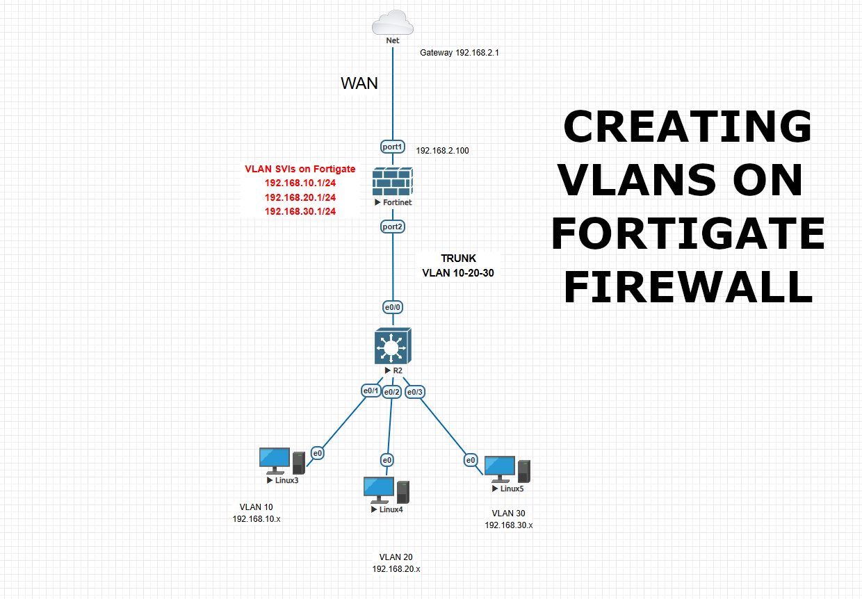
We will create 3 vlans as VLAN 10 – 192.168.10.1/24 , VLAN 20 – 192.168.20.1/24 , VLAN 30 – 192.168.30.1/24 and connect the firewall to switch with trunk port. Then we will set static route and IPV4 policies for internet access and intervlan communication. Also we will create the DHCP servers for each vlan on the firewall. Afterwards we will configure the Cisco L3 switch, we will set trunk and access ports as required also will define vlan ids.
This topology and configuration can be used in some cases, but most of the time this is not a best practice. Because internal LAN traffic should be handled by L3 switch as this is its duty. And only WAN traffic should hit the firewall to optimize the network traffic. LAN traffic should be handled via core switch, WAN traffic should be handled via Firewall in best practices.
This is our general diagram as below
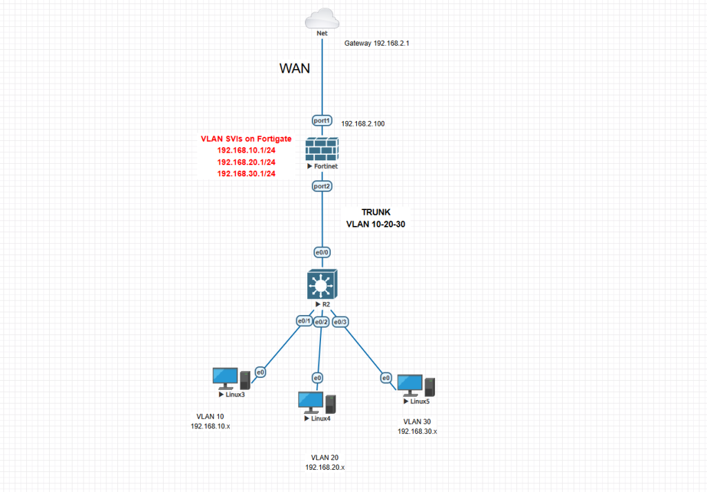
This is our Fortigate initial configuration on CLI to reach it via GUI
FortiGate-VM64-KVM login: admin
Password:
You are forced to change your password, please input a new password.
New Password:*****
Confirm Password:*****
Welcome !
FortiGate-VM64-KVM # config system interface
FortiGate-VM64-KVM (interface) # edit port1
FortiGate-VM64-KVM (port1) # set alias WAN
FortiGate-VM64-KVM (port1) # set role wan
FortiGate-VM64-KVM (port1) # set mode static
FortiGate-VM64-KVM (port1) # set ip 192.168.2.100 255.255.255.0
FortiGate-VM64-KVM (port1) # set allowaccess ssh ping http https telnet fgfm
FortiGate-VM64-KVM (port3) # end
Now we will reach to Fortigate GUI to proceed with configuration. Go to your browser and visit 192.168.2.100 and use the credentials which you created. Initial password is empty and you change it during above configuration.
This is the final look of your interfaces. We will create the interfaces (VLANs) on port2 and configure them under this port. We wont give any IP address to port2 as this will be used as Trunk port between Firewall and Switch.
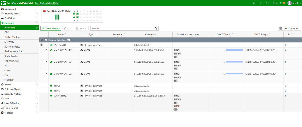
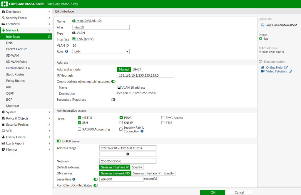
Click on Interfaces from left menu, then click Create New > Interface and configure all your VLANs like as in this example accordingly. Each VLAN has its own SVI IP address. For VLAN10 we will use 192.168.10.1/24 as we will use 192.168.10.0 subnet. So change it accordingly for all vlans. Enable DHCP server as you require. As this a test lab, I enabled all administrative access protocols but do not enable them all for your security.
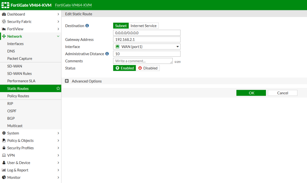
Below you can find the static route configuration. As we have only 1 ISP in this example, we route all the WAN traffic to ISP gateway 192.168.2.1 through WAN port.
Here below you can find the IPV4 policies. Without these policies you cannot reach internet or cannot communicate inter vlans. After completing this configuration, you can be also more specific for some services and restrictions for some IP addresses between VLANs. There are many security features that you can implement.
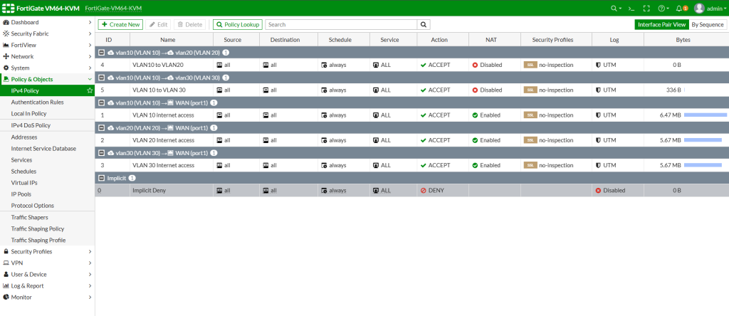
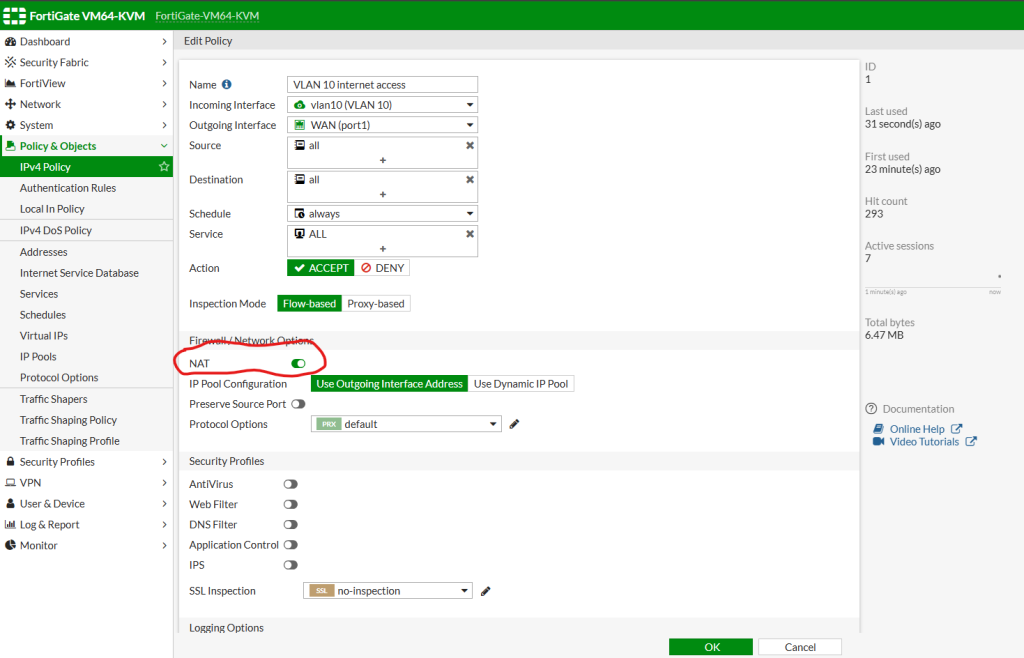
This is your IPV4 policies general look. Lets create a policy for VLAN10 internet access. Then you can follow the same way for your other VLANs as well. For internet access, do not forget to enable NAT service as this is internet access and requires NAT translation outwards.
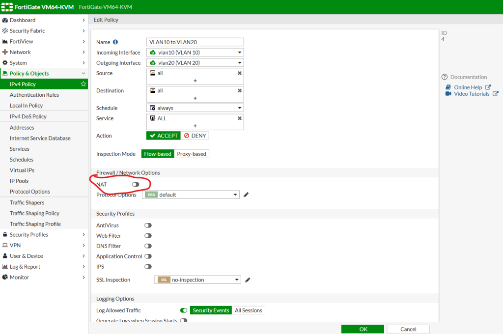
And we need to create another policy for Inter VLAN communication. You can set a policy which allows 1 vlan to communicate with another vlan. And you can also create another policy and put it above this rule to allow only some specific IP address to reach another vlan. For internal VLAN communication we do not need NAT service as this is LAN communication and doesn’t require any translation.
Our Cisco switch configuration is shown as below. No specific thing actually, only 1 trunk port on the switch and the rest is access port. Important thing is to create vlan names so switch can understand the VLAN IDs accordingly. To create VLAN ids, once in configuration mode basically type “vlan 10” and press enter then “vlan 20” and also for 30. then exit and save the config with “copy run start” then configure the ports as below.
CISCO SWITCH CONFIGURATION
Switch>en
Switch#sh run
Building configuration...

Current configuration : 949 bytes
!
! Last configuration change at 18:04:50 UTC Sat Nov 2 2024
!
version 15.1
service timestamps debug datetime msec
service timestamps log datetime msec
no service password-encryption
service compress-config
!
hostname Switch
!
boot-start-marker
boot-end-marker
!
!
!
no aaa new-model
!
ip cef
!
!
no ipv6 cef
ipv6 multicast rpf use-bgp
!
!

!
spanning-tree mode pvst
spanning-tree extend system-id
!
!
vlan internal allocation policy ascending
!
!

!
interface Ethernet0/0
 switchport trunk encapsulation dot1q
 switchport mode trunk
 duplex auto
!
interface Ethernet0/1
 switchport access vlan 10
 switchport mode access
 duplex auto
!
interface Ethernet0/2
 switchport access vlan 20
 switchport mode access
 duplex auto
!
interface Ethernet0/3
 switchport access vlan 30
 switchport mode access
 duplex auto
!
!
no ip http server
!
control-plane
!
!
line con 0
 logging synchronous
line aux 0
line vty 0 4
!
end

Switch#
Now after these configurations you should be able to reach internet and can ping other clients on the network. Please do not hesitate to contact me if you have any questions regarding this implementation.
Happy networking 🙂
