A DNS server, or Domain Name System server, is a crucial component of the internet infrastructure that helps translate human-readable domain names into IP addresses. Domain names are the familiar web addresses that people use to access websites, such as “www.barisyuksel.com.tr“. IP addresses, on the other hand, are numeric identifiers that computers and devices use to communicate with each other over the internet.
When you enter a domain name into your web browser, your device sends a request to a DNS server to resolve the domain name into its corresponding IP address. This process is known as DNS resolution. The DNS server looks up the IP address associated with the provided domain name and returns it to your device, allowing your browser to establish a connection to the appropriate server hosting the website.
DNS servers are distributed across the internet and are organized in a hierarchical manner. There are different types of DNS servers, including:
- Recursive DNS Servers: These are typically provided by your Internet Service Provider (ISP) or other third-party providers. They handle DNS resolution requests from end-user devices and query authoritative DNS servers to retrieve the IP address for the requested domain.
- Authoritative DNS Servers: These servers hold the official DNS records for specific domains. They provide the IP addresses associated with domain names to recursive DNS servers upon request. Domain owners or administrators manage authoritative DNS servers to control the DNS records for their domains.
- Root DNS Servers: These are the top-level DNS servers in the global DNS hierarchy. They store information about the locations of the Top-Level Domains (TLDs), such as “.com,” “.org,” and country-code TLDs like “.uk” or “.jp.” There are only a limited number of root DNS servers, and they play a critical role in directing DNS queries to the appropriate TLD DNS servers.
- TLD DNS Servers: These servers are responsible for storing information about specific top-level domains. For example, “.com” TLD DNS servers hold information about all domain names ending with “.com.”
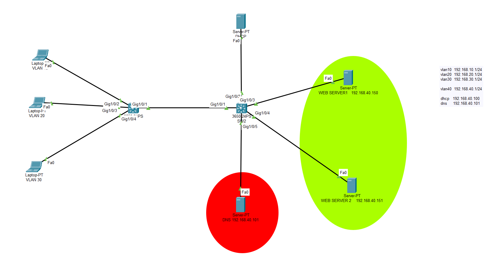
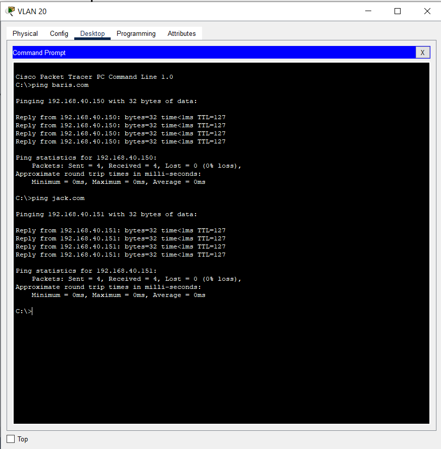
On our topology, we have 2 webservers, 1 dns server, 1 dhcp server, 2 switches, 3 client pcs. We will setup 4 vlans; 1 of them will be used for servers and the rest of them will be used for the clients. If you are familiar with the VLAN definitions please proceed to DNS setup section. After completing all the necessary configurations, from our client pcs we will be able to ping web servers with their DNS records as baris.com or jack.com .
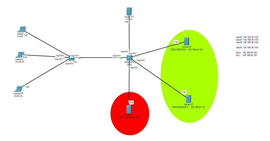
SWITCH 1- CONFIGURATION (SKIP THIS PART IF YOU ARE FAMILIAR WITH VLANS)
Switch>enable
Switch#configure t
erminal
Enter configuration commands, one per line.  End with CNTL/Z.
Switch(config)#vlan 10
Switch(config-vlan)#vlan 20
Switch(config-vlan)#vlan 30
Switch(config-vlan)#vlan 40
Switch(config-vlan)#exit
Switch(config)#int vlan 10
Switch(config-if)#
%LINK-5-CHANGED: Interface Vlan10, changed state to up


Switch(config-if)#ip address 192.168.10.1 255.255.255.0
Switch(config-if)#ip helper-address 192.168.40.100
Switch(config-if)#no shutdown
Switch(config-if)#exit

Switch(config)#interface vlan 20
Switch(config-if)#
%LINK-5-CHANGED: Interface Vlan20, changed state to up

Switch(config-if)#ip address 192.168.20.1 255.255.255.0
Switch(config-if)#no sh
Switch(config-if)#ip helper-address 192.168.40.100
Switch(config-if)#exit


Switch(config)#interface vlan 30
Switch(config-if)#
%LINK-5-CHANGED: Interface Vlan30, changed state to up


Switch(config-if)#ip address 192.168.30.1 255.255.255.0
Switch(config-if)#ip helper-address 192.168.40.100
Switch(config-if)#no shutdown
Switch(config-if)#exit

Switch(config)#interface vlan 40
Switch(config-if)#
%LINK-5-CHANGED: Interface Vlan40, changed state to up

Switch(config-if)#ip address 192.168.40.1 255.255.255.0
Switch(config-if)#no shutdown
Switch(config-if)#ip helper-address 192.168.40.100
Switch(config-if)#no shutdown
Switch(config-if)#exit
Switch(config)#ip routing
Switch(config)#do write
Building configuration...
Compressed configuration from 7383 bytes to 3601 bytes[OK]
[OK]
Switch(config)#interface g1/0/1
Switch(config-if)#sw mode trunk

Switch(config-if)#
%LINEPROTO-5-UPDOWN: Line protocol on Interface GigabitEthernet1/0/1, changed state to down

%LINEPROTO-5-UPDOWN: Line protocol on Interface GigabitEthernet1/0/1, changed state to up

%LINEPROTO-5-UPDOWN: Line protocol on Interface Vlan10, changed state to up

%LINEPROTO-5-UPDOWN: Line protocol on Interface Vlan20, changed state to up

%LINEPROTO-5-UPDOWN: Line protocol on Interface Vlan30, changed state to up

%LINEPROTO-5-UPDOWN: Line protocol on Interface Vlan40, changed state to up

Switch(config-if)#sw trunk allow vlan all
Switch(config-if)#no shutdown
Switch(config-if)#exit

Switch(config)#int g1/0/2
Switch(config-if)#switchport mode access
Switch(config-if)#switchport access vlan 10
Switch(config-if)#no shutdown
Switch(config-if)#exit
Switch(config)#interface g1/0/3
Switch(config-if)#switchport mode access
Switch(config-if)#switchport access vlan 20
Switch(config-if)#no shutdown
Switch(config-if)#exit
Switch(config)#int g1/0/4
Switch(config-if)#switchport mode access
Switch(config-if)#switchport access vlan 30
Switch(config-if)#no shutdown
Switch(config-if)#exit
Switch(config)#do write
Building configuration...
Compressed configuration from 7383 bytes to 3601 bytes[OK]
[OK]
Switch(config)#
SWITCH-2 CONFIGURATION
Switch>enable
Switch#configure terminal
Enter configuration commands, one per line.  End with CNTL/Z.
Switch(config)#interface g1/0/1
Switch(config-if)#switchport mode trunk
Switch(config-if)#switchport trunk allow vlan all
Switch(config-if)#no shutdown
Switch(config-if)#exit
Switch(config)#vlan 10
Switch(config-vlan)#vlan 20
Switch(config-vlan)#vlan 30
Switch(config-vlan)#vlan 40
Switch(config-vlan)#exit

Switch(config)#interface g1/0/2
Switch(config-if)#switchport mode ac
cess
Switch(config-if)#switchport access vlan 40
Switch(config-if)#no shutdon
Switch(config-if)#exit
Switch(config)#interface range g1/0/3-5
Switch(config-if-range)#switchport mode access
Switch(config-if-range)#switchport access vlan 40
Switch(config-if-range)#no shutdown
Switch(config-if-range)#exit
Switch(config)#do write
Building configuration...
Compressed configuration from 7383 bytes to 3601 bytes[OK]
[OK]
Switch(config)#
Switch(config)#
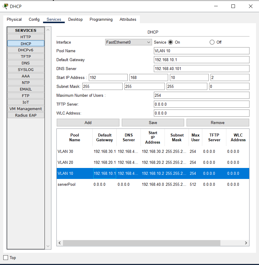
DHCP CONFIGURATION
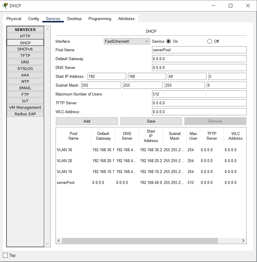
DNS SERVER DEFINITION ON DHCP SERVER
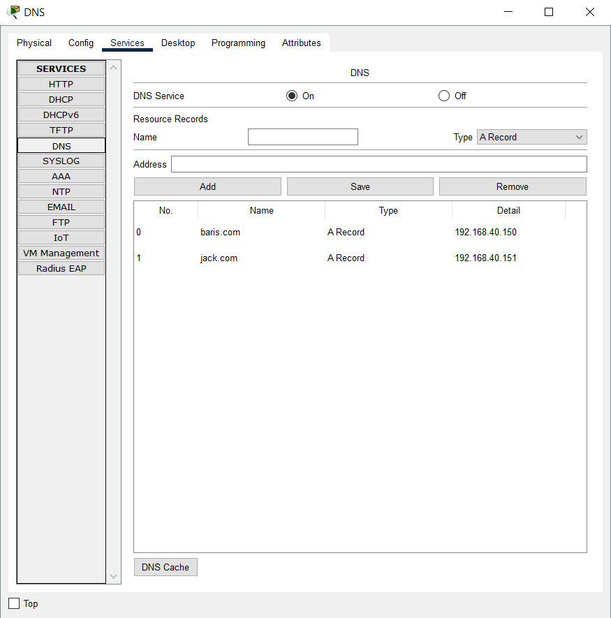
DNS SERVER CONFIGURATION
On our example we have 2 webservers. And we will define A records for both these 2 webservers.
192.168.40.150 >>> baris.com (A RECORD)
192.168.40.151 >>> jack.com (A RECORD)
Once all the configuration is done, we will be able to ping baris.com from the CMD directly.
Now we will try to ping our webservers using their DNS records.
(Fyi: It might take some time to cache the DNS records.)
You can download my simulation from below link.
And run it on Cisco Packet Tracer to inspect in detailed view.
If you have any questions feel free to contact me.
Happ networking 🙂
