Hello everyone,
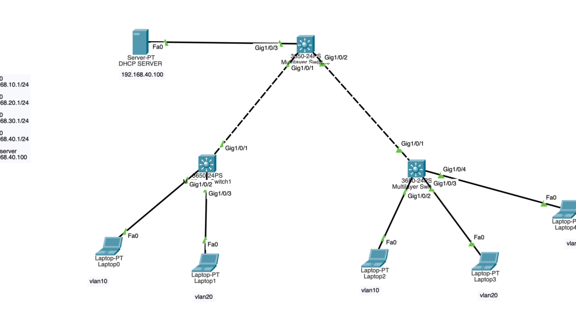
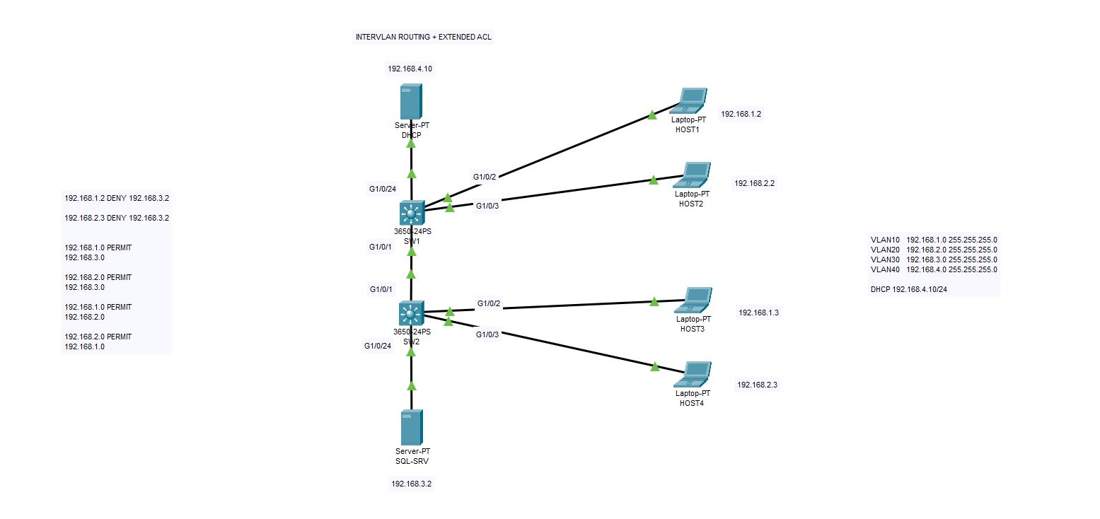
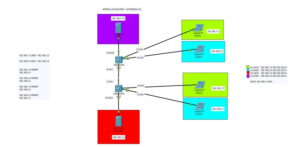
In this example we will create 4 VLANs on a mid-level network infrastructure. Above you can see the logical topology which we created. There is one DHCP server on 192.168.4.10/24 , one SQL-server on 192.168.3.2, four different client hosts and two layer-3 switches.
We will use EXTENDED ACL to create some rules on intervlan communication. Normally without any configuration, VLANs cannot talk to each other. But if we create Intervlan Routing on Layer-3 switch, we enable them to talk each other. And then we will implement some rules to permit or deny access between them.
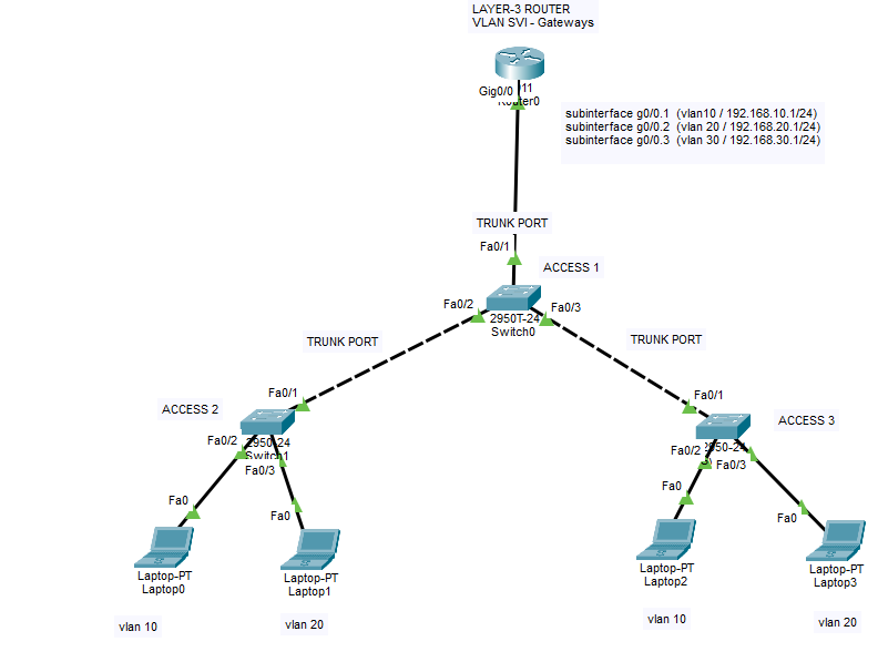
There are several ways for inter VLAN communication. Layer-3 inter VLAN routing and Router on a stick methods are widely preferred methods. Our method is layer-3 inter VLAN routing and for access rules we will use extended ACL.
Let’s get started with creating VLANs,
Switch>en
Switch#configuration terminal
Enter configuration commands, one per line.  End with CNTL/Z.
Switch(config)#hostname SW1
SW1(config)#vlan 10
SW1(config-vlan)#vlan 20
SW1(config-vlan)#vlan 30
SW1(config-vlan)#vlan 40
SW1(config-vlan)#exit
SW1(config)#interface vlan 10
SW1(config-if)#
%LINK-5-CHANGED: Interface Vlan10, changed state to up

SW1(config-if)#ip address 192.168.1.1 255.255.255.0
SW1(config-if)#ip helper-address 192.168.4.10
SW1(config-if)#no shutdown
SW1(config-if)#exit
SW1(config)#interface vlan 20
SW1(config-if)#
%LINK-5-CHANGED: Interface Vlan20, changed state to up

SW1(config-if)#ip address 192.168.2.1 255.255.255.0
SW1(config-if)#ip helper-address 192.168.4.10
SW1(config-if)#no shutdown
SW1(config-if)#exit
SW1(config)#interface vlan 30
SW1(config-if)#
%LINK-5-CHANGED: Interface Vlan30, changed state to up

SW1(config-if)#ip address 192.168.3.1 255.255.255.0
SW1(config-if)#ip helper-address 192.168.4.10
SW1(config-if)#no shutdown
SW1(config-if)#exit
SW1(config)#interface vlan 40
SW1(config-if)#
%LINK-5-CHANGED: Interface Vlan40, changed state to up

SW1(config-if)#ip address 192.168.4.1 255.255.255.0
SW1(config-if)#ip helper-address 192.168.4.10
SW1(config-if)#no shutdown
SW1(config-if)#exit
SW1(config)#
And now we will define the Switch-1’s ports as access and trunk ports as below. As we need to carry multiple VLAN data between switches we need one trunk port and others will be used as access modes. We will use 802.1Q protocol.
SW1(config)#interface g1/0/1
SW1(config-if)#switchport mode trunk

SW1(config-if)#
%LINEPROTO-5-UPDOWN: Line protocol on Interface GigabitEthernet1/0/1, changed state to down

%LINEPROTO-5-UPDOWN: Line protocol on Interface GigabitEthernet1/0/1, changed state to up

%LINEPROTO-5-UPDOWN: Line protocol on Interface Vlan10, changed state to up

%LINEPROTO-5-UPDOWN: Line protocol on Interface Vlan20, changed state to up

%LINEPROTO-5-UPDOWN: Line protocol on Interface Vlan30, changed state to up

%LINEPROTO-5-UPDOWN: Line protocol on Interface Vlan40, changed state to up

SW1(config-if)#switchport trunk allow vlan 10,20,30,40
SW1(config-if)#no shutdown
SW1(config-if)#exit
SW1(config)#interface g1/0/24
SW1(config-if)#switchport mode access
SW1(config-if)#switchport access vlan 40
SW1(config-if)#no shutdown
SW1(config-if)#exit
SW1(config)#interface g1/0/2
SW1(config-if)#switchport mode access
SW1(config-if)#switchport access vlan 10
SW1(config-if)#no shutdown
SW1(config-if)#exit
SW1(config)#interface g1/0/3
SW1(config-if)#switchport mode access
SW1(config-if)#switchport access vlan 20
SW1(config-if)#no shutdown
SW1(config-if)#exit
SW1(config)#
SW1#
Now we will proceed with the second switch configuration,
Switch>enable
Switch#configuration terminal
Enter configuration commands, one per line.  End with CNTL/Z.
Switch(config)#hostname SW2

SW2(config)#vlan 10
SW2(config-vlan)#exit
SW2(config)#vlan 20
SW2(config-vlan)#exit
SW2(config)#vlan 30
SW2(config-vlan)#exit
SW2(config)#vlan 40
SW2(config-vlan)#exit

SW2(config)#interface g1/0/1
SW2(config-if)#switchport mode trunk
SW2(config-if)#switchport trunk allow vlan 10,20,30,40
SW2(config-if)#no shutdown
SW2(config-if)#exit

SW2(config)#interface g1/0/2
SW2(config-if)#switchport mode access
SW2(config-if)#switchport access vlan 10

SW2(config-if)#no shutdown
SW2(config-if)#exit

SW2(config)#interface g1/0/3
SW2(config-if)#switchport mode access
SW2(config-if)#switchport access vlan 20
SW2(config-if)#no shutdown
SW2(config-if)#exit

SW2(config)#interface g1/0/24
SW2(config-if)#switchport mode access
SW2(config-if)#switchport access vlan 30
SW2(config-if)#no shutdown
SW2(config-if)#exit
SW2(config)#
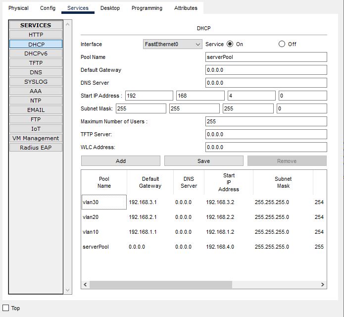
It is time to create DHCP scopes (IP pools) on DHCP server,
Now comes the critical point. Here below you will see the implementation of Extended ACLs. We will implement extended ACL rules to the interfaces of VLANs. We will prohibit 192.168.1.2/24 & 192.168.2.3/24 to communicate with SQL server on 192.168.3.2/24 . We will let other devices to communicate each other. Our ACL is named “IT-ACL” you may name it as you desire.
Also do not forget to apply “ip routing” command, otherwise VLANs cannot communicate each other.
Also you can remove extended access lists with a basic command like “no ip access-list extended IT-ACL”
SW1>en
SW1#configuration terminal
Enter configuration commands, one per line.  End with CNTL/Z.

SW1(config)#ip access-list extended IT-ACL
SW1(config-ext-nacl)#deny ip 192.168.1.2 0.0.0.0 192.168.3.2 0.0.0.0
SW1(config-ext-nacl)#deny ip 192.168.2.3 0.0.0.0 192.168.3.2 0.0.0.0
SW1(config-ext-nacl)#permit ip any any
SW1(config-ext-nacl)#exit

SW1(config)#int vlan 10
SW1(config-if)#ip access-group IT-ACL in
SW1(config-if)#exit

SW1(config)#int vlan 20
SW1(config-if)#ip access-group IT-ACL in
SW1(config-if)#exit

SW1(config)#int vlan 30
SW1(config-if)#ip access-group IT-ACL in
SW1(config-if)#exit

SW1(config)#ip routing
SW1(config)#